Bistable Displays

Bistable displays only require electrical power to change the image being shown — once written, the pixels retain their state indefinitely with no power applied. They are also reflective, using ambient light rather than a backlight. This makes them well suited to low-power applications such as e-readers, electronic shelf-edge labels and signage. This page covers three bistable display families: electrophoretic displays, cholesteric liquid crystal displays (ChLCDs) and zenithal bistable displays (ZBDs).
Electrophoretic Displays
Electrophoretic displays are the most well-known family of bistable displays. They reflect incoming light rather than relying on self-illumination. They are also commonly called E-Paper, EPDs (electronic paper displays), or Active Matrix Electrophoretic Displays (AMEPDs).
Driver or Driverless
An active-matrix electrophoretic display is built from two layers. The backplane is a grid of thin-film transistors (TFTs). There is one per pixel, each with a storage capacitor and pixel electrode. They are addressed by row gate lines and column source lines. The frontplane is the electrophoretic ink film (E Ink calls it the Front Plane Laminate) laminated on top. The TFT backplane only sets a voltage on each pixel electrode and is medium-agnostic — it is the same active-matrix technology used in LCDs and OLEDs. This is why electrophoretic displays inherit TFT terminology (the gate and source drivers, and TFT kickback) and are formally called Active Matrix Electrophoretic Displays (AMEPDs). The drivers address the TFT backplane, while the electrophoretic ink is just the frontplane responding to the resulting pixel voltages. This is only true for larger electrophoretic displays, as small segmented displays (such as price tags and badges) often skip the TFT backplane architecture and just drive each segment directly.
Electrophoretic displays are typically either sold with the driver IC included in the screen, or without it (it which can you have to connect up a suitable driver circuitry yourself). Note that even the driverless electrophoretic displays still have driver circuitry inside them, typically the gate and source driver (which are connected to the pixel array).1 Driverless displays typically have a large pin connector (30-70 pins). For example the E-Ink EC113TC1 electrophoretic display has a 50-pin FPC connector! Driverless displays require significant additional circuitry to work: power management circuitry to generate a range of different voltages that the screen requires, plus a TCON (timing controller) to convert a framebuffer into the appropriate gate/source waveforms.
Just to give you an idea of the voltage rail requirements here is an example of the different voltages required, taken from the TPS65185x PMIC datasheet:2
VPOS: 15 V, 120 mAVNEG: -15 V, 120 mAVDDH: 22 V, 15 mAVEE: -20 V, 15 mAVCOM: Adjustable, 0 to -5.11 V
What is VCOM?
VCOM is the common electrode voltage. This is a single voltage applied to the transparent electrode that sits on the viewing side of an electrophoretic display. It is shared with every pixel. The charged pigment particles in each pixel are moved under an electric field set up between each pixel’s individual electrode on the back side (driven by the source driver) and this common VCOM electrode.
The source driver swings the pixel’s electrode from approx. +15 V to -15 V. VCOM is an adjustable voltage in the range of -5 to 0 V.2 VCOM must be adjustable so that the display sets an average DC voltage of 0 V over time, as residual DC causes ghosting, image sticking and shortens panel life. VCOM is adjusted so that the positive and negative changes to each pixel are balanced. But why is it normally negative, and not a range centered around 0 V (e.g. -2.5 V to +2.5 V)? This is because of TFT kickback (feedthrough) compensation. When a pixel’s TFT gate switches off, parasitic gate-to-source capacitance injects a small “kickback” voltage that shifts the stored pixel voltage by a fixed offset. This offset is a small negative value, so VCOM is offset from 0 V to cancel that.
The optimal VCOM differs slightly from panel to panel (due to variations in the TFT characteristics, cell gap and ink batch), so it is measured at the factory and supplied per-panel. It is typically printed on the FPC tail or stored in an EEPROM. The driver then programs the PMIC’s adjustable VCOM output to that value, which is why the PMIC needs a finely adjustable VCOM rail (and often a VCOM sense/measurement feature to help calibrate it).2
The IT8951 AM type EPD Timing Controller (TCON) is a popular timing controller IC for electrophoretic displays. It comes in a 128-pin QFP package.3 It works with large EPDs up to 2048x2048.1 The TCON is responsible for converting the framebuffer into clocked gate and source driver waveforms expected by the gate and source drivers. It compensates for temperature by applying waveform LUTs based on a temperature sensor near the screen.
Manufacturers
E Ink
E Ink is a brand of electrophoretic display made by the E Ink Corporation. The founders of E Ink Corporation developed the electrophoretic display technology while working at the MIT media lab. E Ink Corporation was founded in 1997 and commercialized this technology.4 E Ink is a commonplace term that is sometimes used to refer to any electrophoretic display.
The E Ink Corporation has displays such as a the E Ink Carta, E Ink Spectra, E Ink Kaleido.4
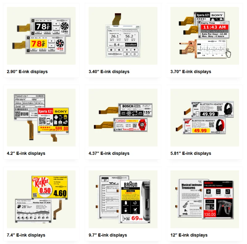
Pervasive Displays
Pervasive Displays is a Taiwan based electrophoretic display manufacturer. One of their unique selling points is extended temperature ranges: to operating, and to storage.5
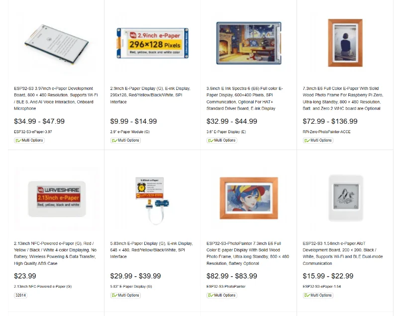
Waveshare
Waveshare is a general purpose electronics hardware company that has a range of electrophoretic displays.
DKE
DKE was founded in 2005 and is a Chinese company that specialises in electrophoretic displays. As of June 2026 they produce a range of black-and-white, 4-colour and full-colour displays in sizes from 0.97 inch to 31.5 inches.8 Most if not all of their electrophoretic displays appear to come bundled with the driver circuitry, with their FPC connector requiring SPI from a microcontroller and some passives for a small section of external power circuitry.
They have a black-and-white “BS” series that has special low temperature ratings down to .
DKE screens are sold on Alibaba.com.
Good Display
Good Display (Dalian Good Display Co., Ltd.) is a Chinese company that produces a range of electrophoretic displays. Their product range includes black-and-white, 4-colour (they call this multi-color), full-colour (Spectra 6) and small flexible electrophoretic displays.9
MpicoSys
MpicoSys produces timing controllers to drive electrophoretic displays. They have three generations of controllers:
- TCM: First generation. It appears this line has been discontinued.
- TCM2: Compatible with 7.8”, 9.7”, 11.3”, 13.3”, 28”, 31,2”, and 42” Eink displays.
- TCM3: Newest generation. Compatible with 13,3” and 28” Eink displays.
Electrophoretic Display Lighting
Light Guide Film (LGF)
Light guide films are thin (typically 0.2-0.5 mm thick) polycarbonate, acrylic or PMMA films that use microdots or laser etched patterns to distribute side-entry light evenly across it’s surface. The light is usually provided by side mounted LEDs. Light reflects internally through the film until it hits the obstructions. These reflect the light out of the display and provide even illumination.
They can be optically bonded to the front of electrophoretic displays, and along with a LED light source, can be used to illuminate the display.
Yongtek and Nanocomp are two companies that makes these films especially for electrophoretic displays.1011.
Cholesteric Liquid Crystal Displays (ChLCDs)
Cholesteric Liquid Crystal Displays (ChLCDs) are bistable displays based on cholesteric liquid crystals (a.k.a. chiral nematic liquid crystals12). Although they are sometimes marketed as a type of E-Paper, they are a distinct technology from electrophoretic displays. Like other bistable displays they do not require a backlight (traditional LCD displays do) and draw little/no power when the image is not changing. Given their wider temperature range than electrophoretic displays, ChLCDs are heavily marketed towards outdoor applications such as signage (e.g. bus stop signs, city information boards, etc).13
Advantages:
Disadvantages:
- Narrower viewing angles
- Worse contrast (compared to monochrome electrophoretic displays)
How ChLCDs Work
Cholesteric refers so molecules which arrange themselves in a certain direction in a layer, and then when these layers are stacked on-top of each other, the direction of each layer slowly rotates to form a helix. The name cholesteric comes from cholesterol, as this behaviour was first observed in derivatives of cholesterol.12

The helical pitch of the molecules can be adjusted to either transmit or reflect specific wavelengths of light.
ChLCDs contain three liquid crystal layers, red, green and blue. Pixels on each layer can be controlled via electrical signals which alter the local electric field around a pixel. Different voltages align the crystals in different ways which changes the optical properties of the layer. The three textures are:
- Planar texture
- Focal conic texture
- Homeotropic texture: The rod-like crystals align perpendicular to the substrate. This allows the light to pass through the layer. If all RGB layers are in this state, the pixel shows the background substrate colour (typically black).15
The full colour spectrum is achieved via the well-used additive principle of the three primary colours from the three layers.
Solar panels can also be placed behind all of the colour layers. If the colour layers are designed to pass infrared light, then a ChLCD can be used as both a display and a power source.15
Suppliers
Iris Optronics Co.
Iris Optronics Co. is a Taiwanese company that manufacturers ChLCDs. They have the following products:
- Full Color ChLCD: A full-colour ChLCD display in 10 inch, 13.3 inch and 31.5 inch sizes.16
- Infinity Display: A colour ChLCD with a solar panel behind it, available in 13.3 and 31.5 inch sizes.
- Ming Display: A full-colour ChLCD with LED based illumination for night viewing.
- ecosticker: A full-colour 10-inch ChLCD display.
Iris Optronics acquired colour reflective ChLCD patents from Fujitsu in 2016.17
AUO Display
AUO Display manufacturers the HiRaso family of ChLCDs.
Zenithal Bistable Displays (ZBDs)
The Zenithal Bistable Display (ZBD — pronounced zebedee18) is another bistable liquid crystal technology that competes with E-Paper. Unlike ChLCDs it uses an ordinary nematic liquid crystal — the bistability comes from a microscopic grating structure on one of the alignment surfaces rather than from the liquid crystal itself.
Advantages:
- Zero power to retain an image (like other bistable displays)
- Built on standard LCD production lines — only one alignment layer is replaced with the grating
- Because pixels latch into a stable state, passive-matrix addressing can drive an arbitrary number of rows without the multiplexing limits of conventional STN LCDs (no TFT backplane needed)
- Faster update rates than electrophoretic displays
Disadvantages:
- Typically monochrome
- Requires polarizers, which reduces reflectivity (paper-like appearance is worse than electrophoretic displays)
- LCD-like viewing angle behaviour
How ZBDs Work
A ZBD cell is constructed like a conventional nematic LCD, except one of the two internal alignment surfaces is replaced with a deep sub-micron grating. The liquid crystal director (the average direction the rod-shaped molecules point in) can sit in two different stable configurations at this grating:
- Continuous state: the director follows the grating surface smoothly and ends up tilted nearly vertically (perpendicular to the substrate).
- Defect state: disclinations (alignment defects) form at the peaks and troughs of the grating, which allows the director to lie nearly flat (parallel to the substrate).
Both states are local energy minima, so the cell holds either one indefinitely with no applied voltage — this is what makes the display bistable. The name zenithal refers to the fact that the two states differ in the zenithal (out-of-plane tilt) angle of the director at the grating surface.
Switching between the states is done with DC pulses, which couple to the flexoelectric polarization of the liquid crystal near the grating. A pulse of one polarity latches the surface into the defect state, and a pulse of the opposite polarity latches it back into the continuous state.18 Combined with a conventional monostable alignment surface on the opposite plate, the two grating states give the cell two different optical configurations (e.g. a twisted nematic-like state and a vertically aligned-like state), which appear black and white between polarizers.
History
The technology was invented at the UK Defence Evaluation and Research Agency (DERA) in the mid-1990s19 and spun out as ZBD Displays Ltd. in 2000, which was rebranded as Displaydata in 2014.1820 The main commercial application has been electronic shelf-edge labels (ESLs) for retail stores.21 In 2019, New Vision Display (NVD) acquired the ZBD technology from Displaydata — including the patents, know-how and the Malvern, UK R&D facility — and continues to offer ZBD LCDs for custom applications. NVD is headquartered in Shenzhen, China.22
Suppliers
ZBD is rather unique in that there seems to be only the one supplier, New Vision Display (NVD). This could be considered a risk when considering using ZBDs for long-term products.
Footnotes
-
zephray. zephray/glider [GitLab repository]. GitLab. Retrieved 2026-05-25, from https://gitlab.com/zephray/glider. ↩ ↩2
-
Texas Instruments (2017, Sep). TPS65185x PMIC for E Ink Vizplex Enabled Electronic Paper Display [datasheet]. Retrieved 2026-06-20, from https://www.ti.com/lit/ds/symlink/tps65185.pdf. ↩ ↩2 ↩3
-
ITE. IT8951 [product page]. Retrieved 2026-05-25, from https://www.ite.com.tw/en/product/cate5/IT8951. ↩
-
Wikipedia (2026, Apr 22). E Ink [wiki]. Retrieved 2026-05-07, from https://en.wikipedia.org/wiki/E_Ink. ↩ ↩2
-
Pervasive Displays (2024, Aug 14). Wide Temperature E-Paper Displays: 5 Key Business Advantages. Retrieved 2026-06-22, from https://www.pervasivedisplays.com/wide-temperature-e-ink/. ↩
-
Pervasive Displays. Products - The Best E-ink E-Paper Displays for Industry and IoT [product page]. Retrieved 2026-05-07, from https://www.pervasivedisplays.com/product/#epds-e-paper. ↩
-
DKE. DKE e-Paper Display Manufacturer [product page]. Retrieved 2026-06-22, from https://dke.top/products/. ↩
-
Good Display (2020, Apr 27). Black & White ePaper [product page]. Retrieved 2026-06-22, from https://www.good-display.com/product/6/. ↩
-
Yongtek. Yongtek E-Paper Front Light — 4.3–32” Standard & Custom Solutions [product page]. Retrieved 2026-05-06, from https://www.yongtek.com/front-light-panel-218p.html. ↩
-
Nanocomp Oy Ltd. Front Light Guide for E-Paper Displays [product page]. Retrieved 2026-05-06, from https://www.nanocomp.fi/products-and-solutions/light-guides-for-displays/front-light-guide-for-e-paper-displays/. ↩
-
Wikipedia (2026, Apr 13). Cholesteric liquid crystal [wiki]. Retrieved 2026-05-18, from https://en.wikipedia.org/wiki/Cholesteric_liquid_crystal. ↩ ↩2
-
AUO Display Plus. HiRaso Display Technology [product page]. Retrieved 2026-05-18, from https://www.auodplus.com/en-global/technology/HiRaso_display_technology. ↩ ↩2
-
IRIS Optronics (2024, Dec 12). Color E-Paper Face-Off: E Ink Gallery vs ChLCD. Retrieved 2026-05-18, from https://iris-opt.com/en/blog/eink-acep-gallery-vs-chlcd/. ↩
-
IRIS Optronics (2025, Sep 15). How ChLCD Works. Retrieved 2026-05-18, from https://iris-opt.com/en/blog/what-is-chlcd/. ↩ ↩2
-
IRIS Optronics. Full Color Cholesteric Liquid Crystal Display (ChLCD) e-Paper Module [product page]. Retrieved 2026-05-18, from https://iris-opt.com/en/products/full-color-chlcd/. ↩
-
IRIS Optronics. Company Introduction. Retrieved 2026-05-18, from https://iris-opt.com/en/about-iris/company-introduction/. ↩
-
J. Cliff Jones (2017, Aug 22). Defects, flexoelectricity and RF communications: the ZBD story [journal article]. Liquid Crystals, 44(12–13), pp. 2133–2160. Taylor & Francis. Retrieved 2026-06-10, from https://www.tandfonline.com/doi/full/10.1080/02678292.2017.1365383. ↩ ↩2 ↩3
-
G. P. Bryan-Brown, C. V. Brown, J. C. Jones, E. L. Wood, I. C. Sage, P. Brett, J. Rudin (1997, May). Grating Aligned Bistable Nematic Device [conference paper]. SID Symposium Digest of Technical Papers, vol. 28, pp. 37–40. Retrieved 2026-06-10, from https://www.researchgate.net/publication/281860799_53_Grating_Aligned_Bistable_Nematic_Device. ↩
-
Fiona Briggs (2014, Jan 17). ZBD rebrands as Displaydata and launches new graphic electronic shelf-edge labels (ESL) [news article]. Retail Times. Retrieved 2026-06-10 (via archive.org, original URL is now dead), from https://web.archive.org/web/20200222224804/http://www.retailtimes.co.uk/zbd-rebrands-displaydata-launches-new-graphic-electronic-shelf-edge-labels-esl/. ↩
-
Bob Raikes (2022, Aug 1). ZBD’s Journey via ESLs to Custom [article]. Display Daily. Retrieved 2026-06-10, from https://displaydaily.com/zbd-s-journey-via-esls-to-custom/. ↩
-
New Vision Display (2019, Sep 20). New Vision Display Acquires ZBD LCD Technology and Malvern, UK Facility [press release]. Display Daily. Retrieved 2026-06-10, from https://www.displaydaily.com/article/press-releases/new-vision-display-acquires-zbd-lcd-technology-and-malvern-uk-facility. ↩