Potentiometers And Rheostats

This page is about mechanically adjustable resistors called potentiometers and rheostats. For fixed resistors, see the Resistors page. For digitally controlled potentiometers, see the Digital Potentiometers (DPOTS) page.
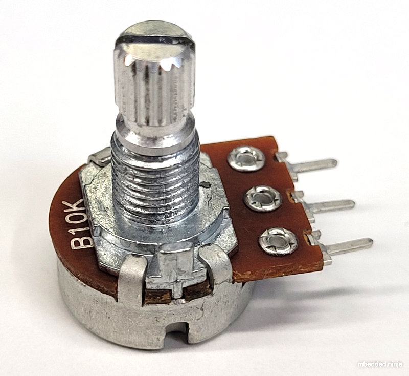
Potentiometers are 3 terminal resistors whose resistance can be varied by means of a mechanical wiper or similar actuating device. They consist of two outer terminals which provide connections to a fixed resistance made from a conductive track, and a middle pin which connects to the wiper. The potentiometer can be turned so that the wiper slides from one end of the track to the other, changing the resistance between it and the two outer pins. A rheostat (which is also called a variable resistor) is simply a potentiometer but with one of the outside pins missing. They typically come in values of 5, 10, 20, 50 and 100kΩ.
Potentiometers are commonly used for user interfaces (e.g. volume control on an audio amplifier), once-off manufacturing calibration, and cheap mechanical rotation to digital converters.
Designator Prefixes And Schematic Symbols
Designator prefixes for potentiometers and rheostats include:
VR(Variable Resistor, my preferred choice)RV(VRthe other way around, KiCAD style)POT
The schematic symbol looks like a normal resistor, but with a third pin added to the side of the resistor with an arrow, indicating the wiper. An example (with the US style squiggly resistor) is shown below:

See the Resistors section of the Component Schematic Symbols and Designators page for more information.
Resistive Track
The resistive track in most cheap potentiometers is made from graphite. Others may be made from carbon or wound wire.
Style
The style of a potentiometer can be:
- Rotary (most common)
- Trimmer
- Slide
Taper
The taper is the relationship between position and resistance. It is also sometimes called the “law”. The taper of a potentiometer can either be:
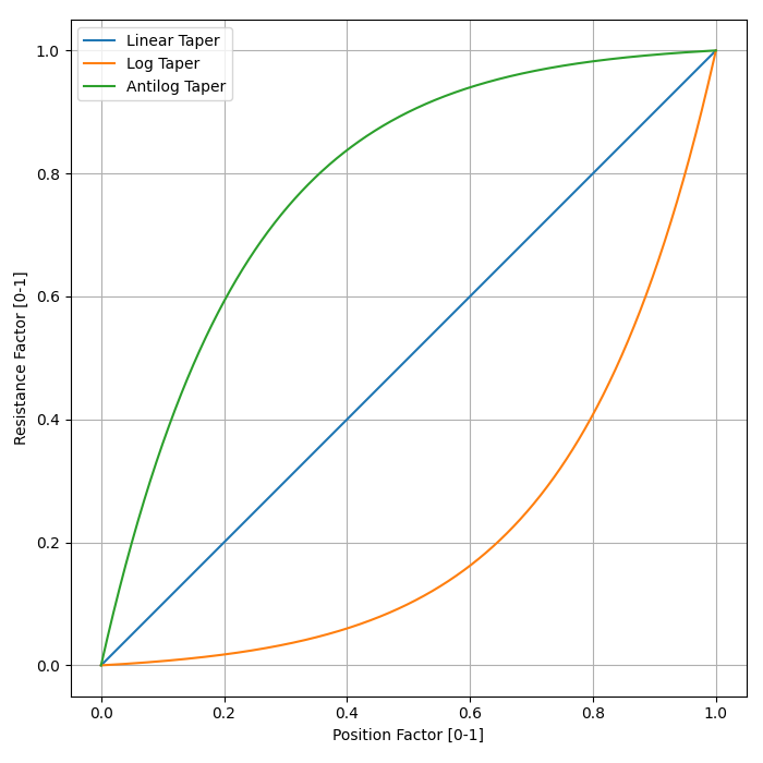
- Linear taper: Most common form of taper. Value changes linearly with knob rotation.
- Logarithmic taper or Audio taper: Commonly used in audio applications for volume control to achieve a more natural change in volume (human ears perceive loudness logarithmically). However, “logarithmic taper” is a misnomer, they are actually exponential (opposite of logarithmic) to compensate for logarithmic hearing!1
- Reverse logarithmic taper: Also called the antilog taper. Exact opposite response of a logarithmic taper pot. Used for applications such as audio volume controls which need to rotate counter-clockwise rather than clockwise.1 These pots actually have a logarithmic response.
The below plot gives you an idea on the shapes of these tapers. For the equation used to generate these tapers, see the below section The Ideal Logarithmic Taper Equation.
Taper codes exist to inform the user of a potentiometers taper. Confusingly, there are many different taper code naming schemes in use, however the Asian version seems to be most common these days1.
| Taper | Asian (common) | Europe | America | Vishay |
|---|---|---|---|---|
| Linear | B | A | B | A |
| Logarithmic (Audio) | A | C | A | L |
| Antilog | F | C | F |
Tapering Resistors
If you can’t get log or antilog potentiometers, you can approximate the behaviour of them using a linear potentiometer and additional fixed resistors (which are called tapering resistors in this context). The below schematic shows how to approximate log, antilog and log-antilog behaviour:
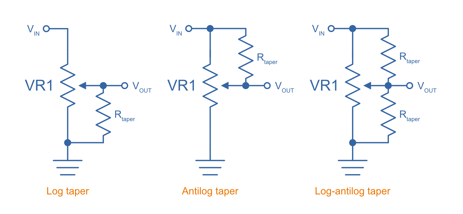
How do we choose the value of ? A good rule-of-thumb is to pick a value which is about 10-20% of the potentiometers total resistance. For example, for a linear potentiometer, you would choose a tapering resistance of . The below graph shows the response of potentiometers with tapering resistors. The tapering resistor’s resistance is 10% of the potentiometers (e.g. if it was a pot, the tapering resistor would be ). In the case of the log-antilog circuit, both tapering resistors have a resistance of 10% . In the case of the log and antilog circuits, the responses are also compared to the “ideal” responses (see The Ideal Logarithmic Taper Equation Section for more on how this is calculated):
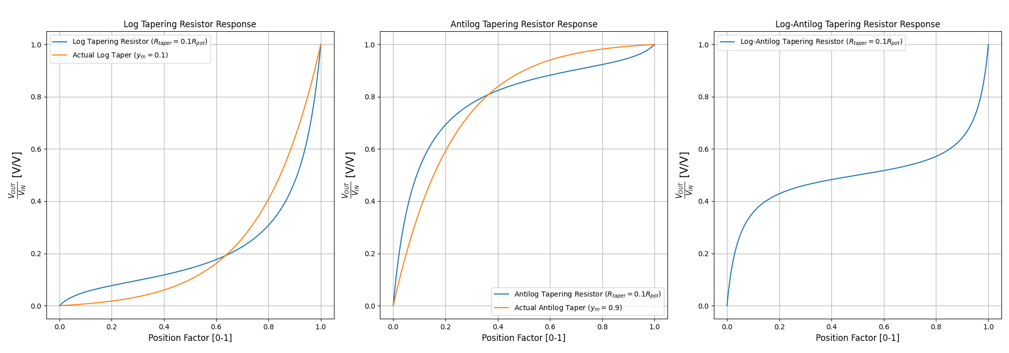
Not bad for 1 or 2 additional resistors! And while yes, you can clearly see differences between the tapering resistor circuit and the ideal responses, in many applications this is close enough (also remembering that many “properly” tapered pots will have similar amounts of difference to an ideal response).
Tolerance And Linearity
Tolerance on potentiometers normally ranges from 2-15%. Note that this is much higher than standard 1% chip SMD fixed resistors, don’t expect potentiometers to be as cheap and accurate!
Precision potentiometers typically focus on achieving what is called good independent linearity. Independent linearity is the maximum deviation from a linear “best fit line” which is plotted against the points comparing the output resistance to the position of the potentiometer2. This best-fit line does not often go through 0.
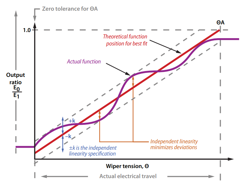
For example, the Bourns 3590S-2-103L 10-turn precision rotary potentiometer has a specified independent linearity of .3
Labelling
Potentiometers are labelled according to their resistance value and resistance layout of the track (taper).
Resistance
The resistance of potentiometers is easy to read, usually indicated by a three-digit number and a multiplier. For example, 100K would symbolise a 100kΩ pot.
Travel (Rotation)
Partial-turn
Partial-turn potentiometers are the most common and cheapest form of potentiometer. The total mechanical travel (rotation) is usually between 250-330°. The total electrical travel is usually less than this, which means there is some dead-zone at the start and end of the travel where the resistance does not change.
Partial-turn potentiometers are commonly used in human-operated situations (the potentiometer is rotated by hand). They provide enough resolution for things such as amplifier volume control.
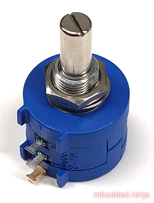
Multi-turn
A common number of turns for multi-turn potentiometers is 10. They are usually MUCH MORE expensive than their partial turn counterparts (as of June 2016, US$20 (100) for a “cheap” 3-turn wire-wound potentiometer).
Multi-turn potentiometers are used when more resolution is required, or the “thing” rotating the potentiometer is going to go through 1 or more revolutions (e.g. if the potentiometer was connected to an axle or pulley which rotated back and forth through 4 revolutions).
Common Uses And Example Circuits
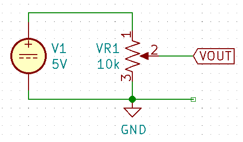
The most common use for a potentiometer to provide a variable output voltage based on how far the potentiometer has been turned. This voltage then can be used to control any number of things, such as the volume of music as the user turns the volume dial. The two ends of the potentiometer are connected across a constant voltage source, in the example below, this is . The wiper then forms the variable mid-point of a voltage divider. As you turn the potentiometer, one of the “resistors” increases while the other decreases, and thus the wiper varies in voltage from one end point to the other. In the example below the wiper voltage varies from to :
A word of caution…Make sure you do not draw too much current from the wiper. Ignoring the wiper resistance, the output impedance of the potentiometer changes depending on the wiper position. When the wiper is at either end, the output impedance is (great you may say). But the output impedance increases to the worst case when the wiper is exactly half-way between the two ends, in which case it is (two resistors in parallel, each resistor being ).
If we assume the worst-case, the output impedance of a potentiometer is:
where:
is the output impedance, in
is the end-to-end resistance of the potentiometer, in
The Ideal Logarithmic Taper Equation
We can write the general equation to map a linear scale to a logarithmic scale as:
Let be the percentage of total potentiometer rotation in where , and be the percentage of total resistance, again varying from . , and are free parameters to fit the desired curve (they are constrained below).
For an ideal potentiometer, we want the resistance to be when the rotation is , e.g. when . Therefore:
This allows us to remove from the equation, giving:
Also, we want to have maximum resistance when the potentiometer is rotated to maximum. So when .
Let’s solve for in terms of :
Substituting into our equation now gives:
We are almost there, except we still have one degree of freedom! How do we choose the value of ? One way is to define the value of when the potentiometer is rotated half-way to max, i.e. at . We’ll call this resistance (y at midpoint).
Let’s solve for :
The below graph shows the shape of the potentiometers response for different values of , starting at and ending with .
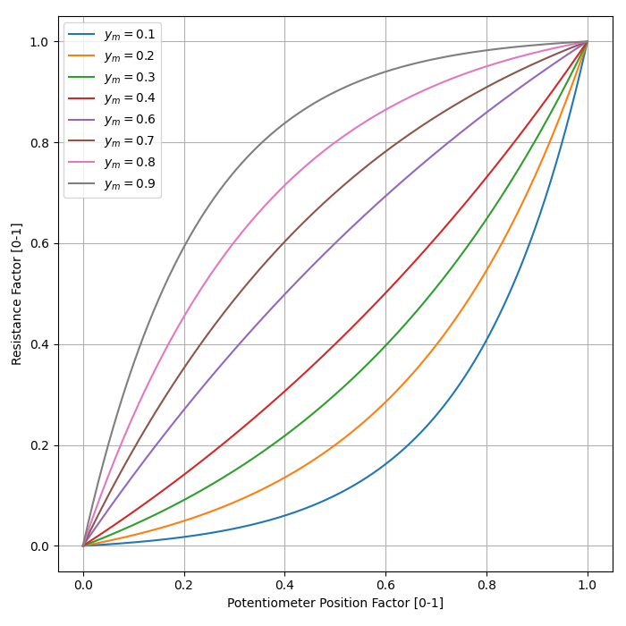
In reality, potentiometers with a “log taper” can be roughly approximated with , whilst those with an “antilog taper” with .
Further Reading
The Potentiometer Handbook by Bourns is a great resource for anything potentiometer related (a hefty 227 pages). Available for free (as of 2022) from https://www.bourns.com/pdfs/onlinepotentiometerhandbook.pdf.
Footnotes
-
EE Power. Chapter 3 - Resistor Types: Potentiometer Taper. Retrieved 2021-12-13, from https://eepower.com/resistor-guide/resistor-types/potentiometer-taper/#. ↩ ↩2 ↩3
-
Bourns. Potentiometers Linearity Technical Note. Retrieved 2022-04-20, from https://www.bourns.com/docs/technical-documents/technical-library/sensors-controls/technical-notes/Bourns_pot_linearity_technote.pdf. ↩ ↩2
-
Bourns. Bourns 3590 - Precision Potentiometer (datasheet). Retrieved 2022-04-20, from https://www.mouser.com/datasheet/2/54/3590-1989906.pdf. ↩
-
Mouser. Bourns 3590S-2-103L (product page). Retrieved 2022-04-20, from https://www.mouser.com/ProductDetail/Bourns/3590S-2-103L?qs=ka0oSW1bB1LlqwdMBlB3qQ%3D%3D. ↩
-
Bourns (2008). The Potentiometer Handbook. Retrieved 2022-04-19, from https://www.bourns.com/pdfs/onlinepotentiometerhandbook.pdf. ↩