Transformers

Transformation Ratio
For an ideal transformer, the voltage of the output (secondary) compared to the input (primary) is directly related to the ratio between the number of turns on the output compared to the input.
Power Equivalence
Remember, energy cannot be created nor destroyed. Therefore, for an ideal transformer, with no losses, the output (secondary) power must be equal to the input (primary) power .
Substituting in the transformation ratio above gives:
Mutual Inductance
In general, the number of mutual inductances that a transformer with N windings has is:
Notice that the number of mutual inductances grows quadratically with .
Coupling Coefficient
The coupling coefficient is usually denoted K. It is used extensively in SPICE simulations.1 The leakage inductance (referred to the winding with inductance ) can be calculated from the coupling coefficient using the following formula:
Non-Ideal Transformer Losses
There are three main types of losses that occur in a non-ideal (real-world) transformer. These are resistive losses, hysteresis losses, and eddy current losses.
In large power transformers, with the appropriate design to reduce the non-ideal losses mentioned below, the efficiency of the transformer can be up around 98%, closely approximating an ideal transformer.
Resistive Losses
These losses occur due to the windings of the transformer having a non-zero resistance. The power lost by resistive losses is:
for both the primary and secondary. For this reason they are also called losses.
Hysteresis Losses
Remember that transformers work with an AC voltage/current. The tiny magnetic domains in the core material are reversed each cycle. This causes losses in the core of the transformer.
The hysteresis loss can be seen on the BH (flux-density vs. field strength) curve.
Eddy Current Losses
Because the core is conductive, it too gets an EMF generated in it, just like the secondary. This causes a current to flow in the core, which is dissipated as heat energy due to the resistance of the core material. To reduce eddy currents, most transformers use a core built up from many laminated sheets of metal, sandwiched between insulating layers.
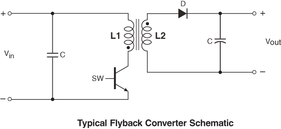
Flyback Transformers
Flyback transformers are transformers used in the construction of a flyback converter, an isolated topology derived from the buck-boost converter. They are also known as switching transformers or SMPS transformers. Because of the way they operate, current does not flow in the primary and secondary windings at the same time. For this reason, it is conceptually appropriate to consider a flyback transformer as two coupled inductors, rather than a true transformer.
Examples of flyback transformers can be found on DigiKey under their Transformers->Switching Converter, SMPS Transformers section.
Footnotes
-
Mike Engelhardt (2006, Sep). Using Transformers in LTspice/SwitcherCAD III [magazine article]. Linear Technology Magazine. Retrieved 2026-07-04, from http://web.archive.org/web/20180127150233/http://cds.linear.com/docs/en/lt-journal/LTMag-V16N3-23-LTspice_Transformers-MikeEngelhardt.pdf. ↩
-
ECE Tutorials. Losses in transformer [article]. Retrieved 2026-07-04, from http://ecetutorials.com/. ↩
-
Coilcraft. A Guide to Flyback Transformers [article]. Retrieved 2026-07-04, from https://www.coilcraft.com/en-us/edu/series/a-guide-to-flyback-transformers/. ↩