USB Charging and Power Delivery

As more and more devices communicate over USB, the same devices are also being designed to be powered/charged over USB (removing the need for a second cable!). It started off with low power devices drawing power from the bus voltage, and has progressed to specific standards being implemented to address the issue of charging power hungry devices (e.g. laptops) over the same USB cables. Many companies have implemented “quick charge” capabilities over USB cables, but the USB Implementers Forum (USB-IF) hopes to standardize charging with the more recent USB Power Delivery standard.
USB power delivery (PD) is a communication protocol and power transfer service designed to work with the USB Type-C connector. Without PD, USB Type-C connectors can provide 5V at 3A (15W). PD allows a power source and sink to communicate with each other and negotiate a higher voltage and/or current, up to a maximum of 20V at 5A (100W), or 48V at 5A (240W) with the Extended Power Range (EPR) mode added in PD 3.1.1 Using Type-C cables to power things is becoming increasingly popular, and the EU has mandated that from 2024 most personal electronic equipment must come with a Type-C charging port.2 And 2 years after that in 2026, laptops must also be chargeable from USB Type-C connectors.
The below table shows a summary of USB specifications and maximum voltages, currents and powers.
| Specification | Max. Voltage | Max. Current | Max. Power |
|---|---|---|---|
| USB 2.0 | 5V | 500mA | 2.5W |
| USB 3.0/3.1 | 5V | 900mA | 4.5W |
| USB BC 1.2 | 5V | 1.5A | 7.5W |
| USB Type-C 1.2 | 5V | 3A | 15W |
| USB PD 3.0 | 20V | 5A | 100W |
| USB PD 3.1 | 48V | 5A | 240W |
Data and Power Roles
In USB terminology, it is important to understand the data and power roles.
There are three data roles:
- Down-stream facing port (DFP): Sends data downstream, e.g. a USB port on your computer (which is acting as a host) or one of the many on a USB hub.
- Up-stream facing port (UFP): Sends data upstream, e.g. a USB mouse, keyboard or camera. UFPs typically act as power sinks.
- Dual-role data (DRD) port: Can act as either a DFP or UFP.
Similarly, there are also three power roles:
- Source: A device capable of providing power onto VBUS, e.g. a USB hub or the host controller that provides the USB ports on your computer.
- Sink: A device which consumes power from VBUS, e.g. a USB mouse or fan.
- Dual-role power: A device that can act as either a source or a sink. A common example is a computer’s USB-C port. When you plug a mouse into it, it powers the mouse, acting as a source. However, many laptops support charging themselves over the same port. If you plug in a USB-C charger, the computer acts as a sink.
Standards
USB Battery Charger Rev 1.2
The USB Battery Charger Rev 1.2 (BC 1.2) was a major upgrade to the specifications in revision 1.0 and 1.1.5 It allows devices to draw up to 1.5A on a fixed 5V (7.5W).6 It was developed to satisfy the need for higher currents than the default 100mA/500mA provided by USB 1.0 and 2.0. Today, it is largely superseded by USB PD (which I would recommend using instead of BC 1.2) for new designs.
There are some standard definitions in the battery charger spec:
- Portable Device (PD): The USB device that is generally portable and is going to receive (sink) current from the USB hub or host.
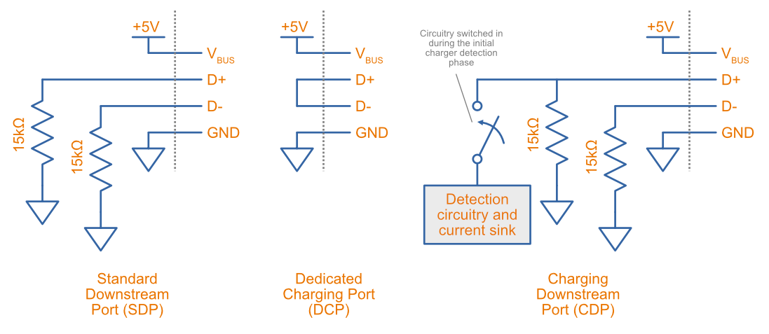
- Standard Downstream Port (SDP): Complies with the definition of a hub or host as defined in USB 2.0.5 Maximum sourced current is 2.5mA when suspended, 100mA when connected, and 500mA when negotiated.
- Dedicated Charging Port (DCP): A port that does not communicate any data, but is solely for providing power for charging (and/or operating). It has to provide between 0.5 and 5A.5 The DCP shorts out the D+ and D- lines, which the device at the other end of the cable can detect.
- Charging Downstream Port (CDP): A mixture of the above two, it both can communicate and provide power at the same levels (1.5A at 5V) as a DCP. Has to provide between 1.5 and 5A.5
The below image shows the basic electrical wiring for the SDP, DCP and CDP ports defined by the BC 1.2 specification:
It’s also important to distinguish between the following terms:
- Attach: The physical process of plugging in a USB cable between two ports.
- Connect: When the PD connects a pull-up resistor to either the D+ or D- line.
- Enumerate: The initial data exchange between the two ports across the data lines.
The PD needs to determine how much current it can draw from the upstream USB port.
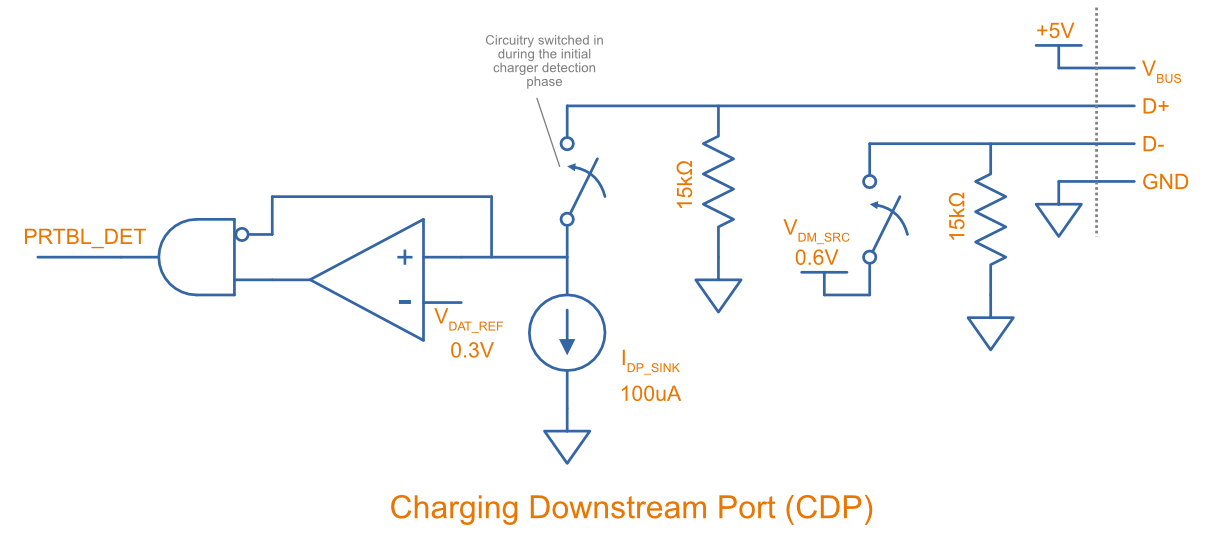
The below image shows the internal circuitry in a Charging Downstream Port (CDP).
USB Power Delivery 1.0
USB Power Delivery 1.0 was released by the USB-IF in July 20127 which offered 5 fixed power profiles. The below table shows the voltages, currents and powers that each profile provides.
| Profile | Voltage | Current | Power |
|---|---|---|---|
| 1 | 5V | 2A | 10W |
| 2 | 12V | 1.5A | 18W |
| 3 | 12V | 3A | 36W |
| 4 | 20V | 3A | 60W |
| 5 | 20V | 5A | 100W |
USB Power Delivery 2.0
USB Power Delivery 2.0 was released alongside the USB Type-C connector specification. It moved the PD communication from the VBUS line (as used by PD 1.0) to the CC lines of the Type-C connector, and replaced the five fixed power profiles of PD 1.0 with more flexible power rules, whilst keeping the same maximum power of 100W (20V at 5A).9
USB Power Delivery 3.0
USB Power Delivery 3.0 made no changes to the maximum power compared to PD 2.0/1.0 (still 100W), but did improve by adding more charging information exchange between the two ports. Information about battery charging status, failures, over-voltages, battery temperatures can be exchanged.9
USB Power Delivery 3.1
USB PD Revision 3.1 was released by the USB-IF in May 2021.10 It increased the max. power available from a USB port from 100W to 240W. It keeps the original spec as per PD 3.0 as part of its Standard Power Range (SPR). Added was the Extended Power Range (EPR) with new fixed voltages of 28V (140W), 36V (180W) and 48V (240W). Also added is an adjustable voltage mode that allows the device being powered to request intermediate voltages (with a 100mV resolution10) between 15V and the max. supported voltage of the charger.1 The power direction was made flexible, allowing hosts and peripherals to both be sources and sinks.1
Communication Protocol
USB PD uses the two CC lines provided in the Type-C connector to perform negotiation between source and sink. The VBUS lines on the Type-C cable plugged into a host/source remain unpowered until a device/sink is plugged in and the CC lines are pulled-down. At this point, VBUS rises to 5V. To get above 5V, more complex digital communications need to occur between the source and sink over the CC lines.
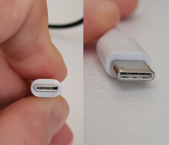
The below image is a photo of a USB Type-C plug on the end of a white cable.
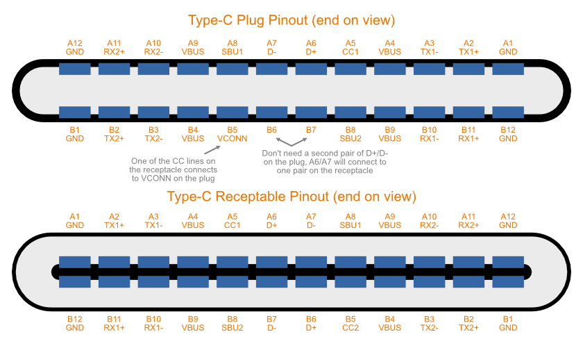
The below image shows the pinout for both the USB Type-C plug and the receptacle.
USB 2.0 Without PD
Before we dive into PD, let’s cover what happens without PD. The most basic powering scenario with Type-C connectors is simple pull-down of the CC lines, leading to 5V being provided on VBUS at either 1.5A or 3A.
The below image shows the basic connections on the CC lines when using USB 2.0 over a Type-C connector.
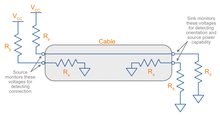
The value of is how the source/DFP advertises its current capability. The sink/UFP always has a fixed value for of . When connected together, they form a voltage-divider. The sink can measure the voltage at the center point and determine the current capability of the source. The below table shows the requirements for .
| Source Current Capability | Current Source to 1.7-5.5V | pull-up to 3.3V ±5% | pull-up to 4.75-5.5V |
|---|---|---|---|
| Default USB power | 80µA ±20% | 36kΩ ±20% | 56kΩ ±20% |
| 1.5A @5V | 180µA ±8% | 12kΩ ±5% | 22kΩ ±5% |
| 3.0A @5V | 330µA ±8% | 4.7kΩ ±5% | 10kΩ ±5% |
The Type-C cable needs to provide a pull-down resistor on its VCONN pin to signal to the source that it needs power. must be between .12 With this resistance, the source can easily tell the difference between which CC pin is connected to the sink and which is the VCONN.
E-markers
E-markers are chips embedded in fancier USB Type-C cables which can inform the source or sink about their capabilities. They are typically embedded in one or both of the ends of the cable. They are required for cables that are designed to go over the standard 3A and provide up to 5A of current.
The e-marker requires power, and it uses one of the CC lines to do so. One of the CC lines is used for communication (which one depends on which way around the Type-C connector is plugged in), and the other is called VCONN and is used to power the e-marker.
It’s a manufacturing choice about whether a cable is provided with just one e-marker at one end of the cable or one at both ends. In the case of just one at one end, a separate VCONN wire must be run the entire length of the cable to bring power to the e-marker from the other end of the cable.
Non-standard Implementations
Qualcomm Quick Charge
Quick charge is designed to work with a number of different connectors, including13:
- USB Type-A
- USB Micro
- USB Type-C
- Proprietary connectors
Example Circuits
Getting Power From a USB Type-C Connector Without Complicated Circuitry
A typical use case when designing an electronic device is that you want it to be powered from a USB Type-C connector, acting as a UFP and power sink. You may not want the cost or complexity of adding a USB PD IC to your circuit design. What options do you have?
The simplest thing to do is to just connect resistors from each CC line to GND. This will allow you to draw 500mA from VBUS without any extra work. In the case where a USB Type-A to Type-C cable is plugged in, and the DFP is a simple USB 1.0/2.0 device, VBUS will be powered automatically and you should be able to draw 500mA without any issues. If a Type-C to Type-C cable is plugged in, the CC resistors will indicate to the connected DFP to power the VBUS. You can again take 500mA without any issues.
Even though USB 3.0 allows more than 500mA, with just two resistors you can’t tell what is connected at the other end of the cable, and so have to design for the limiting case of the DFP being a USB1.0/2.0 device capable of only 500mA.
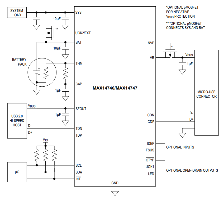
USB Powered Battery Charger with the MAX14747
The Analog Devices MAX14747 is an IC which can detect a number of different USB charger types and charge a battery from the USB power source. It supports USB Battery Charger Detection Rev 1.2 but not USB PD. can range from 0-5.5V so single Li-Po cells are supported. It can be controlled from an MCU via I2C lines.
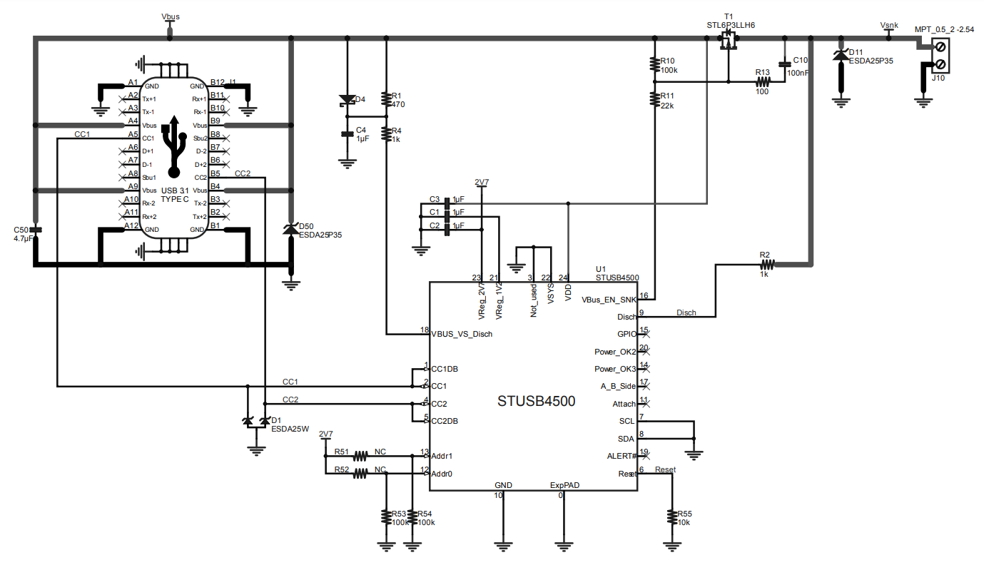
Standalone USB PD Sink Controller with the STUSB4500
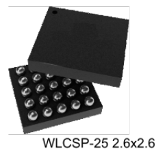
The STMicroelectronics STUSB4500 is a USB PD standalone sink controller. Standalone refers to the fact that it has non-volatile programmable memory that is used to configure the device, meaning the STUSB4500 can run by itself without the need for an MCU to be connected to it. The below image shows a 3D render of it in the WLCSP-25 package.
Below is a minimal application schematic using the IC to act as a USB PD power sink without any connected MCU:
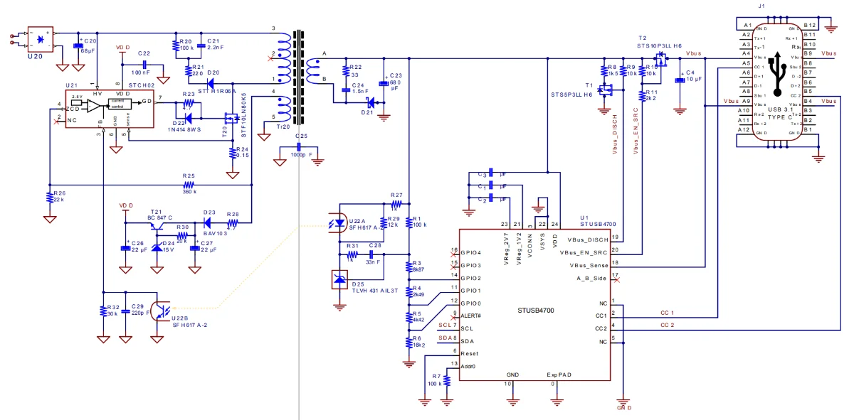
Standalone USB PD Source Controller with the STUSB4700
The STMicroelectronics STUSB4700 is a standalone USB PD controller (i.e. PD source). It is compatible with USB Type-C rev 1.2 and USB PD rev 2.0.16 The below image shows an example application schematic for the STUSB4700 in an isolated flyback converter configuration. This would be a typical design if using this IC to implement a USB wall charger from mains power that is capable of PD.
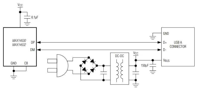
USB Charger Adapter Emulator with the MAX14630
The Analog Devices MAX14630 is designed to be used inside dedicated USB charger adapters with a USB Type A connector. It is a charging adapter emulator in the sense that it detects what is connected to it and pretends to be a charger that is compatible with it. The CB input pin determines the mode of operation:
- Low: Autodetection 2A charger mode. This mode supports USB Battery Charger (BC) rev 1.2 and Apple 2A compliant devices.
- High: Samsung 2A charger mode. This mode supports Samsung 2A compliant devices.
When in autodetection mode, the MAX14630 monitors the voltages on the DM and DP lines to determine the type of device attached. When in Samsung mode, the MAX14630 will monitor the DM line to detect the presence of a Samsung device.17
Connectors
Some USB Type-C connectors do not have all 24 pins available, but just enough to perform charging (basic or PD).
One example is the Molex 2171750001, as shown below:
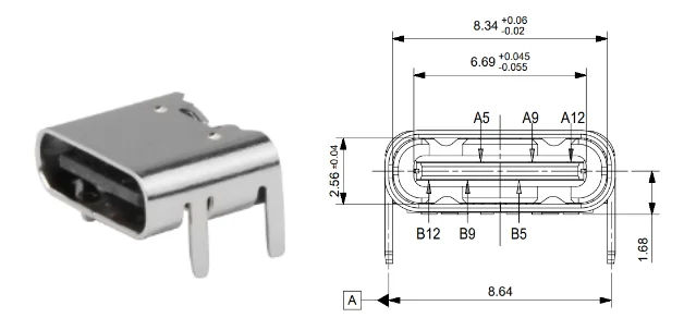
It has a description in DigiKey of: “USB-C (USB TYPE-C) USB 2.0 Receptacle Connector 24 (6+18 Dummy) Position Surface Mount, Right Angle; Through Hole”. The “6+18 Dummy” means only 6 of the 24 contacts are actually provided as SMD leads to the PCB. These are:
A9,B9: VBUSA5: CC1B5: CC2A12,B12: GND
Having VBUS, the CC lines and GND gives you all the leads you need to perform either basic power draw or negotiate higher voltages/currents via the CC lines.
Footnotes
-
usb.org. USB Charger (USB Power Delivery) [web page]. Retrieved 2023-07-07, from https://www.usb.org/usb-charger-pd. ↩ ↩2 ↩3
-
Nick Gelling (2022, Jun). Europe’s new universal charging port rules: how will they affect us? [news article]. Consumer NZ. Retrieved 2023-07-09, from https://www.consumer.org.nz/articles/europes-new-universal-charging-port-rules-how-will-they-affect-us. ↩
-
Nate Enos, Brian Gosselin. A Primer on USB Type-C® and USB Power Delivery Applications and Requirements [pdf]. Texas Instruments. Retrieved 2023-07-07, from https://www.ti.com/lit/wp/slyy109b/slyy109b.pdf. ↩
-
Wikipedia (2023, Jun 29). USB-C [wiki]. Retrieved 2023-07-07, from https://en.wikipedia.org/wiki/USB-C. ↩ ↩2
-
usb.org (2012, Mar 15). Battery Charging Specification (Including errata and ECNs through March 15, 2012) - Revision 1.2 [specification]. Retrieved 2023-07-29, from https://www.usb.org/document-library/battery-charging-v12-spec-and-adopters-agreement. ↩ ↩2 ↩3 ↩4 ↩5
-
Eaton (2023). USB Charging and Power Delivery [web page]. Retrieved 2023-07-28, from https://tripplite.eaton.com/products/usb-charging. ↩
-
Renesas. USB Power Delivery: Enhanced Convenience in USB Charging [web page]. Retrieved 2023-07-09, from https://www.renesas.com/us/en/support/engineer-school/usb-power-delivery-01-usb-type-c. ↩
-
Manhattan. USB-C Power Delivery [web page]. Retrieved 2023-07-09, from https://manhattanproducts.eu/pages/usb-c-pd-charging-everything-you-need-to-know. ↩
-
The Phone Talks. USB PD 2.0 vs 3.0 vs 3.1 Comparison - How Far Have We Come? [web page]. Retrieved 2023-07-09, from https://www.thephonetalks.com/usb-pd-2-0-vs-3-0-vs-3-1/. ↩ ↩2
-
USB Promoter Group. USB Promoter Group Announces USB Power Delivery Specification Revision 3.1 - Specification defines delivering up to 240W of power over USB Type-C [pdf]. Retrieved 2023-07-07, from https://www.usb.org/sites/default/files/2021-05/USB%20PG%20USB%20PD%203.1%20DevUpdate%20Announcement_FINAL.pdf. ↩ ↩2
-
STMicroelectronics. TA0357 - Overview of USB Type-C and Power Delivery technologies [technical article]. Retrieved 2023-07-08, from https://www.st.com/resource/en/technical_article/ta0357-overview-of-usb-typec-and-power-delivery-technologies-stmicroelectronics.pdf. ↩
-
Infineon (2015, Apr 17). Termination Resistors Required for the USB Type-C Connector – KBA97180 [forum post]. Retrieved 2023-07-08, from https://community.infineon.com/t5/Knowledge-Base-Articles/Termination-Resistors-Required-for-the-USB-Type-C-Connector-KBA97180/ta-p/253544. ↩
-
Qualcomm. Qualcomm Quick Charge FAQs [web page]. Retrieved 2023-07-09, from https://www.qualcomm.com/products/features/quick-charge/faq. ↩
-
Maxim (now Analog Devices) (2017, Nov). MAX14746/MAX14747 - USB Detection with Smart Power Selector Li+ Chargers [datasheet]. Retrieved 2023-07-26, from https://www.analog.com/media/en/technical-documentation/data-sheets/MAX14746-MAX14747.pdf. ↩
-
STMicroelectronics (2022, Nov). STUSB4500 - Standalone USB PD sink controller with short-to-VBUS protections [datasheet]. Retrieved 2023-07-26, from https://www.st.com/resource/en/datasheet/stusb4500.pdf. ↩ ↩2
-
STMicroelectronics (2023, Aug). STUSB4700 - Stand-alone autonomous USB PD controller with short-to-VBUS protections [datasheet]. Retrieved 2025-07-22, from https://www.st.com/content/ccc/resource/technical/document/datasheet/group3/4a/1f/85/85/57/7d/41/b7/DM00356577/files/DM00356577.pdf/jcr:content/translations/en.DM00356577.pdf. ↩
-
Analog Devices (2013, Mar). MAX14630/MAX14632 USB Charger Adapter Emulators [datasheet]. Retrieved 2025-07-22, from https://www.analog.com/media/en/technical-documentation/data-sheets/MAX14630-MAX14632.pdf. ↩ ↩2
-
Molex. TYPE C 6 PIN TOP MOUNT SMT - Product Customer Drawing [mechanical drawing]. Retrieved 2023-08-02, from https://www.molex.com/content/dam/molex/molex-dot-com/products/automated/en-us/salesdrawingpdf/217/217175/2171750001_sd.pdf. ↩