1-Wire Protocol

The 1-Wire protocol is a single-wire, half-duplex, bi-directional, multi-drop, wired communication protocol.
| Num. Dedicated Communication Wires | 1 |
| Num. Extra Wires | 1 (0 if parasitic power is supported) |
| Duplex | Half-duplex |
| Directionality | Bi-directional |
| Configuration | Multi-drop |
| License | Proprietary |
| Max. Data Throughput | 16.3 kbps (standard), x10 this on “overdrive”1 |
| Max. Node Distance | Up to ~300 m (with reduced pull-up resistance)1 |
The 1-Wire communication protocol is a hardware and software design that allows communication between a microcontroller and other ICs, using only a single wire (excluding ground, and if needed, a power rail). Each and every 1-Wire IC has its own unique code.
Addressing
Each 1-Wire slave device has a unique, unchangeable 64-bit ID which serves as its address on the 1-Wire bus. Part of this 64-bit address is an 8-bit family code, which identifies the device type/functionality.
The 1-Wire protocol has a unique discovery system in which the master can search and discover the addresses of all slaves on the bus, without knowing any information (like how many slaves there are) beforehand.
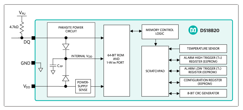
Parasitic Power
To obtain true 1-Wire communication (excluding ground), some 1-Wire ICs support powering over the data line (parasitic power).
To do this, the devices have an internal capacitor (usually 800pF), which stores energy from the data line when it goes high. For reliable power over data communication, the data line cannot stay low (a long run of zeros) for too long.
The disadvantages of parasitic power:
- A MOSFET is required to drive the DQ line to Vcc (bypassing the pull-up resistor) when the 1-Wire device requires high current (such as writing to its internal EEPROM, or performing a temperature measurement).
- This MOSFET switching requires a not-that-simple control algorithm on a microcontroller (or similar).
- The pin of the 1-Wire device has to be connected to GND, which if you can’t do right at the device, requires you to run three wires to the PCB anyway, which can defeat the purpose!
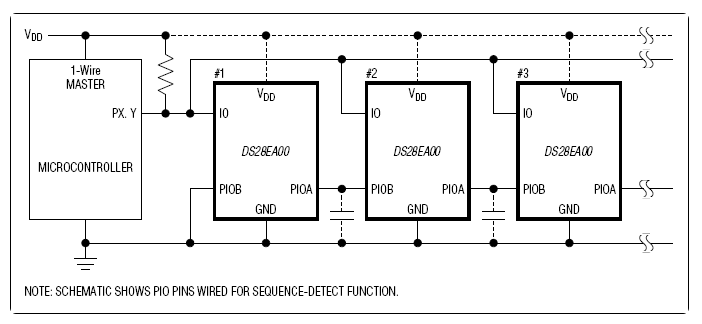
Sequence Detection
Although the standard 1-Wire bus allows the master to search and discover an arbitrary number of 1-Wire slaves on the bus, it does not allow the master to determine the physical sequence in which they are connected (e.g. which one is closest to the master). This can be useful for certain applications.
Some 1-Wire devices have two additional pins to support sequence detection.
Bit Bashing
Bit bashing the 1-Wire interface is possible, but not recommended, due to its asynchronous nature and associated tight timing constraints.
As of October 2015, the Cypress PSoC 3, PSoC 4 and PSoC 5 LP microcontroller families do not have a 1-Wire hardware component, and so bit-bashing is the only option.
Uses
- Digital temperature sensors (especially distributed temperature sensor networks, because of 1-Wire’s multi-drop and discoverable slave capability)
- EEPROM
Footnotes
-
Wikipedia (2025, Oct 16). 1-Wire [wiki]. Retrieved 2026-06-03, from https://en.wikipedia.org/wiki/1-Wire. ↩ ↩2