Tools

Descriptions, usages, pictures and more info of various tools used by embedded engineers.
Benchtop Power Supplies
Benchtop power supplies (PSUs) (plural, you almost always need more than one!) are a essential part of any electronics workshop/lab.
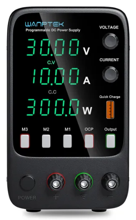
Wanptek 30-160V 10-3A 300-360W PSUs
If you are looking for a good but cheap bench-top DC power supply, the Wanptek range is pretty good. They cost approx. US$50-$80 depending on the variant, as of Dec 2023. They come in a number of different max. voltage/max. current configurations including:
- 30V, 5A (150W)
- 30V, 10A (300W)
- 60V, 5A (300W)
- 120V, 3A (360W)
- 160V, 2A (320W)
Be careful with the 120V and 160V versions, they are high enough to give you a decent electrical shock! 120V is right on the limit of what is considered “extra low voltage” by the IEC, UK IET and AS/NZS 30001. You can set both voltage and current limits to essentially operate in both CV and CC modes. There are some two different UI variants, one which is slightly more expensive and contains three memory buttons (and a slightly different UI).
They are available on AliExpress from https://www.aliexpress.com/item/1005003151034729.html.
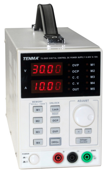
Tenma PSUs
Tenma PSUs are more generally more expensive than AliExpress PSUs but are still cheap compared to the more expensive brands. They are available from Newark/Element14.
The TENMA 72-2925 is a adjustable 0-30V, 0-10A benchtop power supply. As of Dec 2023 it costs approx. US$230.
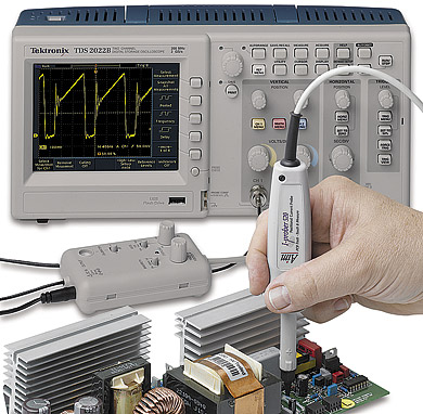
Oscilloscopes
An oscilloscope (or just scope) is to an electrical engineer what a hammer is to a builder. It is a general purpose tool which lets you view voltages (and currents) in a circuit over time. It’s cheaper counterpart is a digital multimeter, however they can typically only display the voltage with an update rate of a few Hertz, and only display a discrete value, not the waveform over time. Oscilloscopes can also measure much faster signals and much faster rates and trigger (take a snapshot) on specific conditions. They typically also have multiple input channels (at least two) so you can compare two voltage waveforms side-by-side.
Mixed-signal oscilloscopes (MSOs) measure both traditional analogue signals as well as digital signals.
Oscilloscope Specifications
Bandwidth
The bandwidth of a scope defines the range of frequencies it can measure. The upper limit is defined when the observed signal drops by -3dB (drops to 70.7%) of the true value. Because all oscilloscopes start measuring at DC (0Hz), this also defines the highest frequency the scope can measure. El cheapo scopes have a bandwidth of 100MHz.
Probes
- Passive: Non-powered
- Active: Powered with active buffering and/or amplification of the signal within the probe itself (before it gets to the oscilloscope).
10:1 probes are the industry standard. Almost all oscilloscopes have an input impedance of when looking into the connector on the front panel of the scope.
Capacitance increases when you go from 10:1 to 1:1. e.g. a 10:1 passive probe may have 10pF of capacitance while an equivalent 1:1 probe may have approx. 100pF. You also lose some input resistance, e.g. it drops from to .
1:1 probes can be good for measuring small levels of noise as they effectively increase the minimum resolution of the oscilloscope by 10 (compared to a 10:1 probe).
Probe Compensation
Some scope probes allow you to adjust the probes compensation.
Without the variable capacitor, the resistance of the probe combined with the resistance and capacitance of the scope will create a low-pass filter that will greatly distort high frequency measurements. The variable capacitor is added in parallel with the probe resistance so that there is both a resistive and capacitive potential divider. The capacitance is then adjusted so that both the resistor divider and capacitor divider have the same division ratio. This ensures the response of the probe is flat across the frequencies of interest.
Maths Functions
I have never had great success using the maths functions on a scope to measure differential signals (by using two single-ended inputs and subtracting one from the other).
Manufacturers
Keysight
Mid to high-end scope manufacturer, in the same class as Tektronix.
Tektronix
Mid to high-end scope manufacturer, in the same class as Keysight.
Tenma
Low-end scope manufacturer.
Multimeters
Multimeters are multi-purpose electrical measurement devices used by both electricians and electronics engineers (among other disciplines).
Some multimeters are designed for electricians (people who deal primarily with 240VAC), which are not as suitable for electronics engineers.
Ghost Voltages (Low-Impedance Voltage Measurements)
Typically, voltage measurements are done at the highest-impedance achievable () by the multimeter so that the multimeter does not effect the circuit it is measuring. However, this can sometimes lead to “ghost voltages”. This is when a real but high-impedance voltage is present on a circuit, normally due to the circuit picking up noise from near-by circuits via phenomenon such as capacitive coupling. This voltage, although real, is misleading as it does not represent the voltage a load (or person getting a shock) would actually see. For this reason these voltages are called ghost voltages.
Some newer digital multimeters come with a low impedance voltage measurement mode to ignore these ghost voltages. This is especially useful for when working with mains power (115/240VAC) and trying to determine if a voltage on a wire is a significant danger or not. Examples of multimeters which have a low-impedance voltage measurement setting include the Fluke 117 Digital Multimeter.
Older, analogue multimeters are not as susceptible to the ghost voltage problem as they typically have a lower impedance when measuring voltages, normally around .
Low-impedance mode should not be used when working with sensitive, small-signal circuitry. The low-impedance of the multimeter might draw enough current to disrupt the circuit and will give you incorrect readings.
All-In-Ones
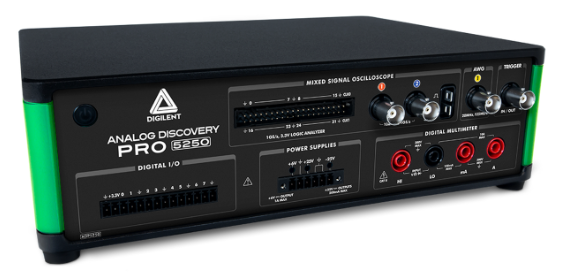
Analog Discovery Pro 3000
The Digilent Analog Discovery Pro 3000 series is an combined benchtop oscilloscope, function generator, I/O, and protocol/logic analyser. The ADP3450 is the cheaper member in the family, and the ADP5250 is the more expensive unit with additional power supplies, but lacks a 4-channel option.
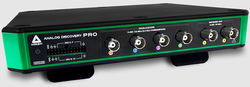
The oscilloscope in the ADP3x50 has a bandwidth of 55MHz. Not as great as the 100MHz you usually get with low-end dedicated oscilloscopes, but still good enough for most general-purpose work. The max. sample rate is 1Msps The WaveForms SDK can be used to control the Analog Discovery Pro via software. Supported languages include C++, C# and Python[^digilent-analog-discovery-pro-ref-manual].
471-040: ADP3450, 4ch, with BNC probes.410-394: ADP3450, 4ch, without BNC probes.471-058: ADP5250, 2ch, with BNC probes.
As of Aug 2022, the ADP3450 with BNC probes retails for NZ$2,453.19 on Mouser, and NZ$2,582.30 on DigiKey.
AC/DC Electronics Loads
A AC or DC _Electronic Load (a.k.a. Active Load) is a piece of electronic test equipment which can act as either a programmable resistance, voltage sink (voltage source, but can only sink power, not produce it) or current sink. They act as a load by converting the incoming electrical power into heat, just like a resistor. However, rather than using a standard fixed resistor (or sequence of switched fixed resistors), they typically use a transistor(s) to dissipate the energy so that it’s “resistance” can be changed electronically, hence why they are also known as active loads. They are usually designed to dissipate 100’s of Watts or more of power (depending on the model). They are separated into two distinct families:
- DC electronic loads (the most common variety)
- AC electronic loads
AC and DC electronic loads are used to:
- Load up power supplies to test their response under a range of operating conditions (incl. 0A to full current, and 0V to highest voltage)
- Act as constant-current sinks to drive LEDs when performing testing/design validation.
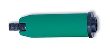
TekBox TBOH02
The TekBox TBOH02 DC load is a great, simple, low-cost DC load. It is self-powered, meaning it powers itself from the energy dissipated via the “load” it pretends to be. 25W continuous power dissipation with no fan, 100W with fan. The advantage of it being an analogue, self-powered load means that there will be no digital/PSU/control-circuitry noise superimposed onto the measurements you are making.
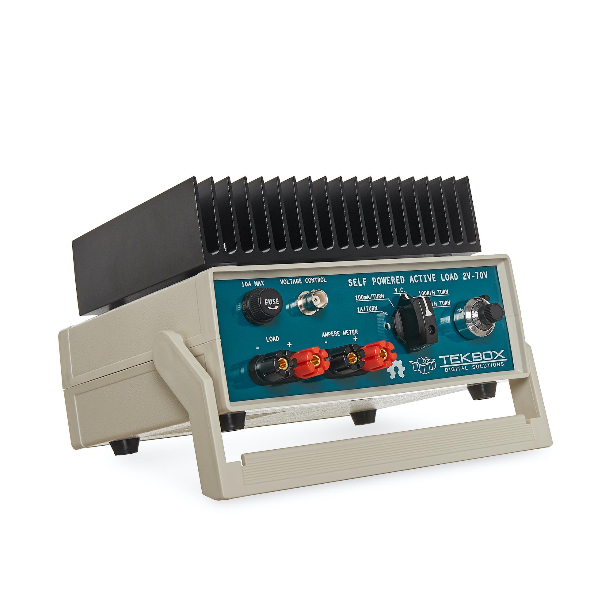
This device is open-source hardware (design is based of https://www.edn.com/precision-active-load-operates-as-low-as-2v/, however EDN’s link to the PDF/schematics is broken as of 2021-06-22), the full schematics, board files and BOM are provided at https://www.tekbox.com/product/tboh02-self-powered-active-load/. Schematics and board files are in the Eagle file format.
USB-to-Serial Converters
FTDI Converters
FTDI (Future Technology Devices International Ltd.) is a popular and reputable designer and manufacturer of USB-to-Serial converters. They make a range of ICs for this purpose, as well and manufacturing useful products which use these ICs (such as USB-to-serial cables).
As of 2016, their ICs are commonly found in good quality USB-to-serial hardware (more so than one of their main competitors, Prolific).
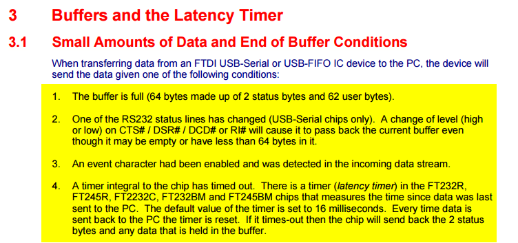
Latency
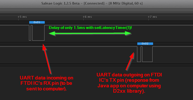
USB-to-Serial converters introduce a fair bit of delays into serial communications. and depending on your latency requirements, this may effect your design.
The below image is a screenshot of FTDI RX/TX data captured with a logic analyser. The computer was running Java code which sent an 0x02 response as soon as it received an 0x01 byte.
Drivers
FTDI provides the Java D2xx API for Android systems. The API is packaged into a file called d2xx.jar and can be downloaded from http://www.ftdichip.com/Android.htm.
Basic information on the driver software can be found at http://www.ftdichip.com/Support/Documents/TechnicalNotes/TN_147_Java_D2xx_for_Android.pdf.
LISNs
A line impedance stabilization network (LISN) is a tool used when performing EMC/EMI tests. A LISN is essentially a low-pass filter placed between a power source and the DUT (device under test).
A LISN performs the following functions:
- Provides a well-known impedance to the power input of the DUT.
- Prevents high-frequency noise from the power supply entering into the DUT, making the measurements of the DUT seem worse than they actually are (isolation of the power supply).
A “50uH” LISN is a common choice, which provides impedance control down to 10kHz. Below 10kHz, impedance control is difficult6.
MIL-STD-461E mandates the use of LISNs to control the impedance of power sources for many of it’s measurement procedures:
The impedance of power sources providing input power to the EUT shall be controlled by Line Impedance Stabilization Networks (LISNs) for all measurement procedures of this document unless otherwise stated in a particular test procedure. — MIL-STD-461E, Section 40.3.6 (4.3.6): Power source impedance
CISPR 25
CISPR 25 sets limits and procedures for the measurement for EMI in the frequency range of 150kHz to 2.5GHz7. Among other utilities, the standard is applicable to vehicles, and it is a popularly referenced standard among automobile electronic design. It specifies the uses of a LISN when performing EMI measurements, is one of the main reasons you will see LISN devices available for purchase.
The TexBox TBOH01 (5uH LISN) is a LISN designed to be compliant with CISPR 25, and retails for around US$250.
Microscopes
Digital
Digital microscopes are a great tool to have on an electronics workbench. Coupled with a screen, they allow you to look up close at a PCB without having to peer down the sights of a optical microscope.
- Depth-of-field: The larger the depth of field, the less zooming you have to do to get different height components and tracks on your PCB into focus.
Optical (Analogue)
AmScope 7X-45X Simul-Focal Stereo Lockable Zoom Microscope on Dual Arm Boom Stand
This a great, well-weighted optical microscope for electronics lab use. The adjustable boom makes it easy to swing the microscope.
Link: https://amscope.com/products/sm-4ntp
Recommended accessories:
- 144 LED Intensity-adjustable Ring Light for Stereo Microscopes with White Housing: https://amscope.com/products/led-144w-zk. This illuminates the work area and gives you great shadow-free light to look at the object at.
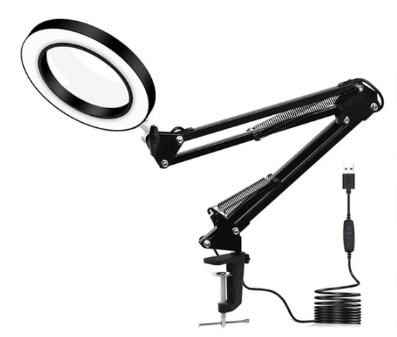
Desk Lamp with Magnifying Glass
Another useful tool to have on your workbench is a desk lamp with a magnifying glass. Generally they have a relocatable magnifying glass on a flexible arm coupled with a illuminating ring around the perimeter of the magnifying glass. They are great for inspecting PCBs and for looking through when soldering small SMD components (as well as checking your rework after you have done it).
These magnifiers are pretty cheap and can be found from many vendors. My favourite in New Zealand is this one shown below from Mighty Ape, which as of April 2024 only costs NZ$55. It is USB powered (which surprisingly gives a good amount of light!) and has in-cable controls to control the light intensity and colour (from yellow to white).
You can also get larger “dentist” style versions of these with longer booms, but for a larger price.
Reflow Ovens
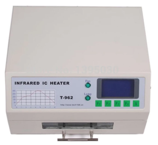
The Infamous Puhui T-962 (and variants)
The Puhui T-962 (and T-962A, T-962C variants) are cheap static desktop reflow soldering ovens.
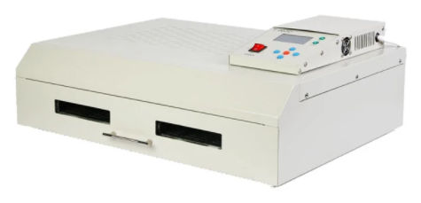
The T-962A has the same design except is a larger unit and provides and effective soldering area of 300x320mm.
| Model Number | Rated Power | Panel Area | Cost (1, approx.) | Image |
|---|---|---|---|---|
| T-962 | 800W | 180x235mm | US$200 | |
| T-962A | 1500W | 300x320mm | ||
| T-962C | 2900W | 585x400mm | US$750 |
It appears there are “2020 New Versions” of the above reflow ovens which have exhaust pipe brackets added onto the back so you can clamp on a pipe to vent exhaust fumes.
It is known to produce bad-smelling fumes when in use, especially when it is new. This is because the manufacturer uses aluminium tape and masking tape in the unit which is not designed for high temperatures, which melts!!! It is recommended to replace the masking tape with kapton tape after purchase (see the upgrade section below for more info).
Third parties have made “upgrade kits” for these reflow ovens which aim to to provide better thermal control of the soldering process and improve the UI experience. For example, ES Technical provides upgrade packages for both the T-962 and T-962A. UnifiedEngineering redesigned the firmware to run on the existing microcontroller, with the hardware addition of a temperature sensor for cold junction compensation.
Clones? The Atten AT-R3028 looks VERY similar to the T-962.
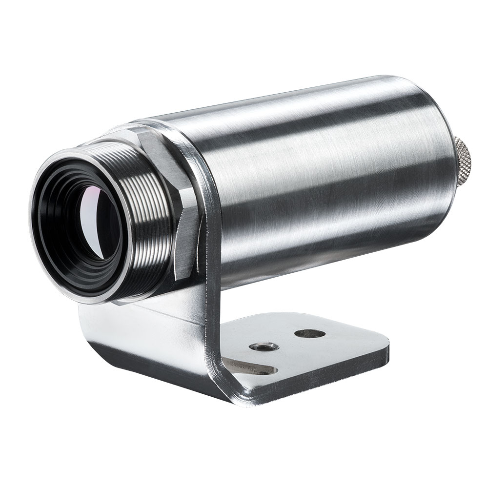
Thermal Cameras
Thermal cameras are great tools to have in an electronics lab for inspecting the thermal behaviour for PCBs and other electrical devices. They can be used to:
- See how heat spread across a PCB
- Detect if things are getting too hot
- Work out where heat sinking is needed
- Calculate thermal resistances.
- Find short-circuits
In the context of hand-held thermal cameras, 80x80 is a small number of pixels, 160x120 is moderate, and 640x480 is a large amount.
Parameters
NETD: Noise Equivalent Temperature Difference: This is the minimum temperature difference that is resolvable by the camera. You could think of this as the sensitivity. It is bad practise to refer to this as the resolution as this will get confused with the pixel (spatial) resolution. NETD of thermal cameras is typically between 100-500mk (100-500m°C). The NETD is measure by pointing the camera at a very stable and uniform black body at a specific temperature. The NETD is the standard deviation of the varying pixel values recorded by the camera over a specific period of time9.
Brands
Keysight
Keysight has one range of handheld thermal cameras called TrueIR. Within this range there are 3 separate devices, with the key difference between them being the maximum measurement temperature. They all have a medium resolution of 160x120 pixels.
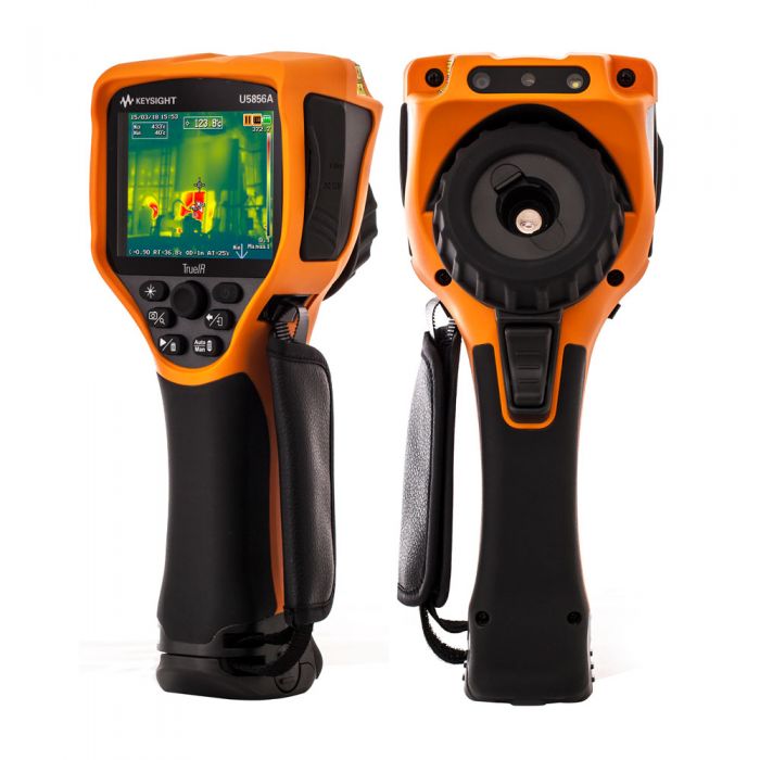
A unique selling point of the Keysight TrueIR range is the small minimum focal distance of 100mm (most other hand-held thermal cameras have a minimum focal length of 300-500mm), which makes them especially useful for inspecting PCBs.
The 350C camera (U5855A) starts at about US$2500, going up to US$3500 for the 1200C camera (U5857A).
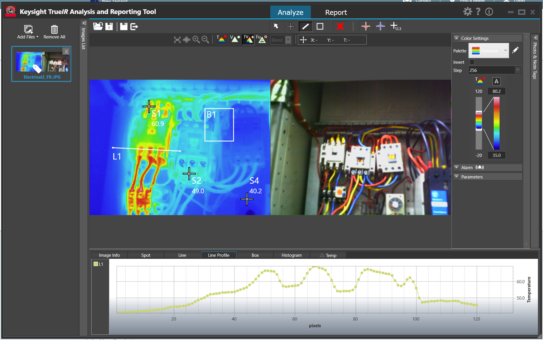
Software
TrueIR Analysis And Reporting Tool
Windows only. Includes ability to stream video from the IR camera when plugged in via USB cable.
FLIR
I was not impressed with the FLIR software (called Fluke Connect Desktop). It took account registration and email link clicking to even get to the point to be able to download it. I then encountered issues installing it without having and old version of Microsoft Word present (the software was looking for this so it could generate reports).
Fluke
Optris
Testo
Testo 865: 160x120 pixels, measurement range -20 to 280°C. Testo 868: 160x120 pixels, measurement range -50 to 650°C.
Minimum focal distance of 0.5m, not so suitable for viewing PCBs.
“SuperResolution” takes the raw infrared pixel resolution of 160x120 and upscales it to 320x240pixels. However I’m not sure how more advanced this is other than just up-sampling the image in the digital realm.
Software
IRsoft
RS Pro
RS Pro is RS Components self-owned brand.
Signal Generators
Output Voltage Not What You Expect?
Most signal generators have a “Load Impedance” setting. Whilst the signal generator almost always has an output of , the signal generator will take this load impedance setting into account and generate a voltage that will result in the set peak-to-peak/amplitude at the output.
However, if this load impedance setting is set to say, 50R, but connected to a high-impedance load (for example, connected straight up to the oscilloscope), you will measure twice the expected voltage at the output!
Ultrasonic Cleaners
Fill up with mixture of water and detergent. Standard kitchen detergent will do. Expensive cleaning solutions aimed at the professional electronics market. Do they perform any better?
GT Sonic Ultrasonic Cleaner 6L: Large enough for most PCBs.
Synergy Electronics Ltd, NZ supplier of the GT Sonic range.
Components That Don’t Like Ultrasonic Baths
- MEMS Oscillators: Ultrasonic cleaners can cause permanent damage or long-term reliability issues to the MEMS resonator inside a MEMS oscillator.
- Crystal Resonators (XTALs): The ultrasonic bath could excite a XTAL into a resonant frequency (or harmonic) that causes damage. 32.678kHZ crystals are especially sensitive since they operate at about the same frequency as an ultrasonic bath uses for it’s cleaning action. MHz XTALs are far less sensitive.
Soldering Irons And Stations
- Quick-change tips
- Maximum heating power
- Heating rate (high quality soldering irons can heat-up to the set temperature within about 2 seconds!)
- Stable temperature control under different loads
For all but the lightest of work you will want to choose a soldering station instead of a soldering iron. The station provides a holder for the iron, keeping it in a safe place while you do other work (so you don’t burn yourself!). It also allows to a lighter and higher power iron, as most of the electronics can now be located in the freestanding control unit rather than in the handheld iron.
Brands
Hakko
An American company with a vivid and memorable blue/yellow brand color.
JBC
The creme-de-la-creme of soldering iron brands. JBC makes some of the highest-quality soldering stations, but as expected, this comes at a very high price.
Weller
The Weller brand is associated with quality, second only to JBC. Naturally, their products are generally cheaper than JBCs to compensate.
Hobbyist Range
Hakko FX888D
No quick change tips
Weller WE1010
No quick change tips
Professional Range
Hakko FM203-15
A dual port soldering station. For use with the FM-2027 soldering iron which takes the Hakko T12 range of tips. Note that the T12 range are quick-change, and you start paying more than double for quick-changes tips (versus the T18 range).
Note that that tips are not truly quick change until you also purchase extra Soldering Pencil Sleeves. These are proprietary hand-grips that slide onto the tip. Once each tip has one of these, you can quickly change tips by unclipping the sleeve + tip from the rest of the iron and inserting a new one. These sleeves also remove the need for using pliers or a rubber mat to remove hot tips.
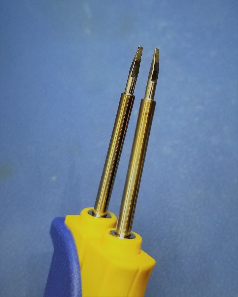
This soldering station can also accept Hakko tweezers. A great choice for popping off and on small 0402/0603/0805 chip resistors and capacitors is the FM-2023 Mini SMD Hot Tweezers with the T9-1L tips:
Weller WT 1010
Single port. 95W. 550°C max temp. For use with the WTP90 soldering iron, which takes the XT tips.
Weller WT2010M
Dual port. 75W x2 450°C
Preheating Stations
Most heater elements are between 600-1200W. The body material of the heating element is usually ceramic.
Yihua UYUE
PUHUI T-862
Adjustable temp. range from 0-450°C.
GORDAK 853
250x220x110mm 600W
PJLSW
430x350x180mm
Current Probes
Current probes are measurement devices which are used to measure the current flowing through a conductive material, typically a wire or track on the PCB (usually with an appropriate connection loop).
The main disadvantage with a hall-effect or transformer-based current-probe is that the probe tip must encircle the conductor under test. To do this you must use a wire, or provide a special PCB cut-out around the current-carrying trace. Fluxgate magnetometer-based current probes do not have this issue.
A typical current-probe will add a few nH of inductance to the conductor under test. Any additional wire added to the conductor to accommodate the current-probe might add around 10nH per centimetre.
The sensitivity of a current probe can be increase by increasing the number of turns of the wire. Be careful to divide the displayed current on the oscilloscope by the number of turns to get the actual current. Note that increasing the number of turns increases the insertion impedance (the inductance rises with the square of the number of turns).
Price
Current probes are not cheap! They are significantly more expensive than their voltage-measuring brothers. As of 2016, you can find cheap no-brand ones for US$60-700, and more expensive Tektronics or Keysight Technologies (the new Agilent) current probes for US$1000-8000.
Hall-Effect Probes
Hall-effect current probes use the hall-effect phenomenon to measure the current travelling through a conductor. Their main advantage over the transformer-based current probes is that they can measure DC currents. However, they do not perform well at higher frequencies (20kHz seems to be a rough upper limit).
The hall-effect sensor is an active sensor, and therefore the probe requires an external power source. This may be provided by an internal replaceable battery (e.g. 9V battery), and external power supply connector, or from the oscilloscope through a specialised connector (this is common on the more expensive, brand specific ones).
Like the AC transformer-based current probes, they require the wire to be inserted into a loop.
Standard AC/DC Current Probes
A combined AC/DC current probe is the most versatile current measurement probe. Traditionally, it uses a transformer to measure AC current, and a hall-effect sensor to measure DC currents (originally patented by Tektronics). Hall-effect sensors are active sensors, so AD/DC current probes require a power source.
The probes are normally split-core, which allows you to open the probe tip up to inset the wire under test.
AC/DC probes output a voltage which is proportional to the current flowing through the wire under test. This voltage is measured by the oscilloscope and displayed on a current-scaled waveform. High-end current probes which are built for specific oscilloscopes may draw power from the single oscilloscope connection, as well as automatically changing the units on the scope and auto-scaling.
Fluxgate Magnetometer Current Probes
The main advantage is that the measuring device does not need to fully encircle the track/wire under test, and you can design a probe-styled instrument that can measure track/wire current just by bringing the probe tip into close proximity.
Aim I-Prober 520
Aim has patents around it’s fluxgate magnetometer based current probe, so it might be a while before other manufacturers make similar probes.
EM Probes
Beehive Non-contact EM Probes
The Beehive Electronics probes set contains three H-field probes (100A, 100B, 100C) and one E-field probe (100D). All are non-contact probes.
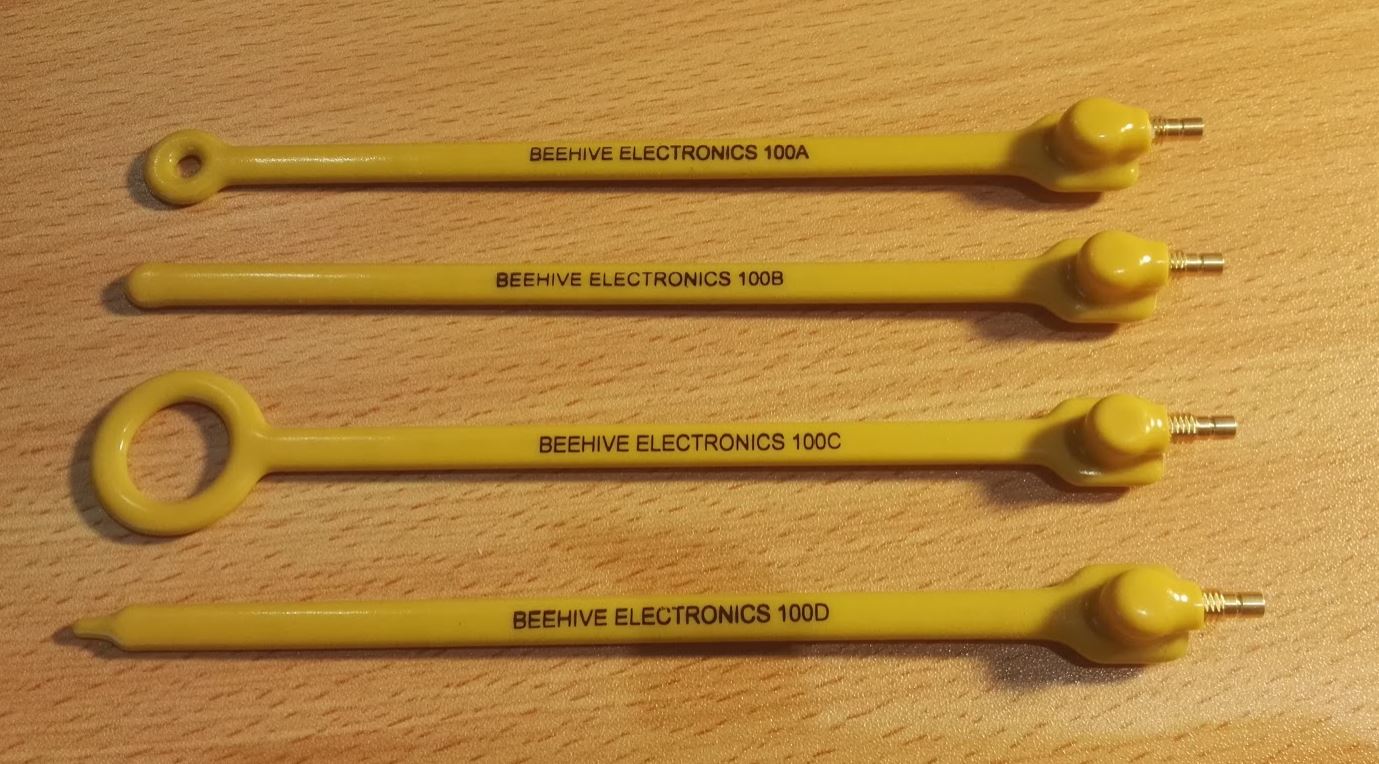
The magnetic flux density can be calculated for the H-field probes using the equation below:
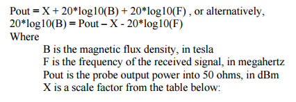
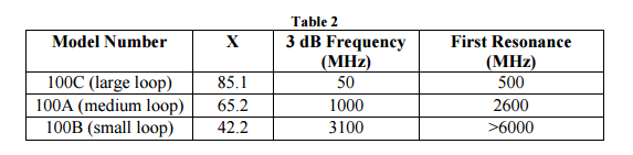
The scale factors for each of the magnetic probes is given below:
Flux
Flux is a substance used in the soldering process to remove metal corrosion and improve the adhesion of the molten solder to the metal surfaces.
Solder Compatibility
Typically, fluxes are compatible with a broad range of solder compounds, including both leaded and higher-temperature lead-free solders.
Activity
Flux activity is a measure of the strength/aggressiveness of the flux in it’s ability to clean metals while soldering. Low activity fluxes are weak fluxes and as usually mild acids. High activity fluxes are strong fluxes and are usually low pH acids.
Types Of Flux
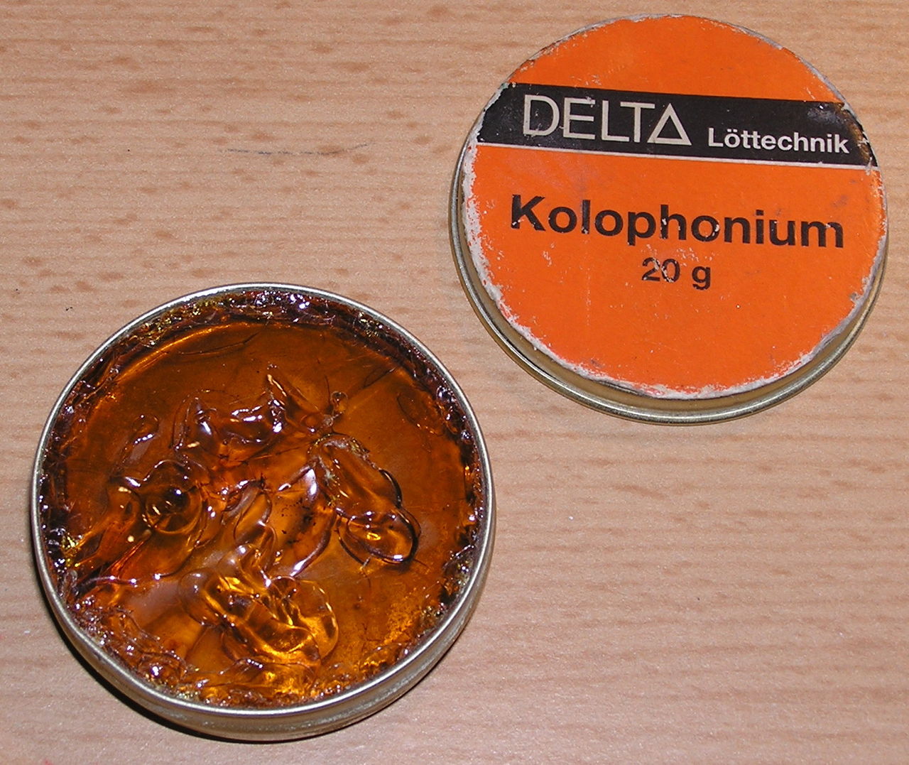
Rosin Flux
Rosin fluxes are the oldest types of flux (well, charcoal was first!). Rosin is the name of refined pine sap. Rosin flux is typically a solid at room temperature, but quickly melts and flow easily at soldering temperatures. It is usually a light or dark amber colour. Rosin fluxes have a low flux activity.
As such, it is usually inert while as a solid, and therefore safe to leave on the PCB after soldering. This is of course unless during normal operation the PCB temperature rises enough to melt the rosin flux.
Rosin fluxes are usually non-polar and therefore cannot be washed off with plain water. Non-polar solvents like isopropyl alcohol, acetone, or paint thinner can be used to clean rosin fluxes. Semi-aqueous solvents or water with
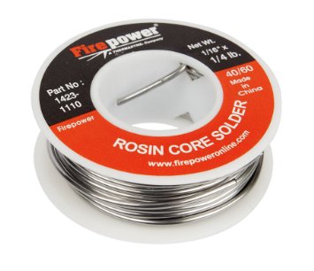
Some types of solder contain a rosin core to aid the soldering process, and saves you time because you do not have to apply the flux manually.
For the chemically-minded people, rosin flux usually has a formula of:
Obviously, being a naturally produced substance, the make-up of a rosin flux will change.
Organic Acid Flux
Organic acid flux is typically made of a weak, organic-based acid such as citric, lactic or stearic acid. The acid is dissolved in a solvent such as a mixture of isopropyl alcohol and water.
They can be a good compromise between reliability, flux activity and cleanability.
Inorganic Acid Flux
The most aggressive type of flux, inorganic fluxes are usually a blend of aggressive chemicals such as hydrochloric acid, zinc chloride and ammonium chloride. They have a high activity. They are normally used for non-electronics related soldering such as a joining of copper pipes (also called brazing).
Inorganic acid fluxes should not be used for electronic soldering because they can leave chemically active residues which cause reliability problems.
”No Clean” Flux
The term “no clean” flux is used for fluxes whose residue will not effect the long-term reliability of the PCB. The two important qualities
A disadvantage of no clean flux is the poor aesthetics of leaving the flux residue on the PCB, it can make the PCB appear dirty, old, and may give people the perception that the build quality is not high (only relevant if people actually see the PCB during it’s normal use).
The IPC-610 standard specifies some the required properties of no clean flux to be compliant.
Flux Applicators
Syringes
Flux can be shipped in a syringe. The syringe tip is either a large-diameter (compared to most medical syringes) metal or plastic needle. Syringes offer more precise application of flux than a syringe pen or rod.
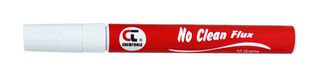
Pens
Flux pens are permanent marker (“sharpies” for all the Americans) sized pens which contain flux inside them. The tip is made from a porous material which applies flux to the surface and draws more up via the capillary action (much like a normal pen). To promote proper flowing, fluxes used in flux pens are typically of a lower viscosity than the ones in syringes or standard containers.
Flux pens are great to have on the work bench for quick, on-off flux applications for reworking. The tips are usually quite thick and do not offer the same precision as flux syringes, but normally this extra precision is not necessary (flux can be “slopped” around the board with little consequence).
Soldering Fumes
During the soldering process fumes are released. The amount of fumes increases drastically as flux is used.
It is generally not a good thing to inhale these fumes on a long term basis. Fume extractors can be used to remove the fumes safely.
Cables
I recommend have a variety of banana plug and crocodile clip cables on hand for development. Stackable banana cables are great as you can plug multiple male plugs into a single female socket. This is great for things like power supplies in where you may need to feed 3.3V to 5 different places.
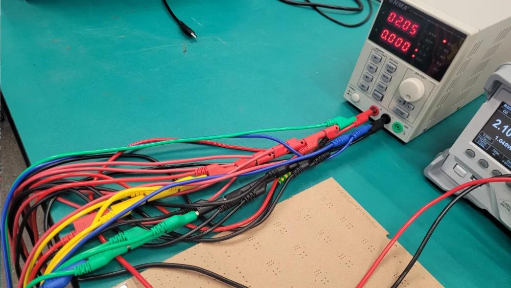
I recommend making a few custom banana to ferrule cables. Get a banana to banana cable, cut one end off, and crimp a ferrule on the end. This then allows you to connect from lab equipment such as power supplies and DC loads straight into lever nut connectors (i.e. WAGO connectors). Then use lever connectors (because they are quick, support many-to-many connections, and it’s easier to add a ferrule to any old wire than it is to solder on a banana socket) for the rest of your interconnects between various power rails, grounds, sensors and other wiring.
Footnotes
-
Wikipedia (2023, Dec 12). Extra-low voltage. Retrieved 2023-12-29, from https://en.wikipedia.org/wiki/Extra-low_voltage. ↩
-
Wanptek. Wanptek Programmable DC Power Supply WPS3010H Laboratory Maintenance Workbench 30V 10A Voltage Current Regulator AC 220V 110V. AliExpress. Retrieved 2023-12-29, from https://www.aliexpress.com/item/1005003151034729.html. ↩
-
Element14. TENMA 72-2925 - Bench Power Supply, Digital Control , Adjustable, 1 Output, 0V, 30V, 0A, 10A [Product Page]. Retrieved 2023-12-29, from https://nz.element14.com/tenma/72-2925/dc-power-supply-1-ch-30v-10a-prog/dp/254306301. ↩
-
Digilent. Analog Discovery Pro (ADP3450/ADP3250) Reference Manual. Retrieved 2022-08-09, from https://digilent.com/reference/test-and-measurement/analog-discovery-pro-3x50/reference-manual. ↩
-
Digilent. Analog Discovery Pro (ADP5250) Reference Manual. Retrieved 2022-08-09, from https://digilent.com/reference/test-and-measurement/analog-discovery-pro-5250/reference-manual. ↩
-
Department of Defense (1999, August 20). MIL-STD-461E: Requirements for the Control of Electromagnetic Interference Characteristics of Subsystems and Equipment. Quick Search. Retrieved 2021-06-30, from https://quicksearch.dla.mil/qsDocDetails.aspx?ident_number=35789 ↩
-
IEC (2016). Vehicles, boats and internal combustion engines - Radio disturbance characteristics - Limits and methods of measurement for the protection of on-board receivers. Retrieved 2021-07-02, from https://webstore.iec.ch/publication/26122. ↩
-
Mighty Ape. Foldable Illuminated USB Magnifier - Black [product page]. Retrieved 2024-04-28, from https://www.mightyape.co.nz/product/foldable-illuminated-usb-magnifier-black/35641740. ↩
-
MoviTHERM. What is NETD in a Thermal Camera?. Retrieved 2020-09-03, from https://movitherm.com/knowledgebase/netd-thermal-camera/. ↩