SMPS Control Methodologies

Switch-mode power supplies (SMPS) generally have to have some sort of feedback-based control loop to regulate the output to the desired voltage (or current). This is called the control methodology. There are a few important types of control methodologies that we will cover on this page.
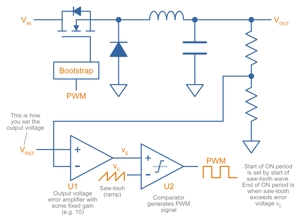
Voltage Mode Control
Voltage mode control (a.k.a. duty-cycle control1) uses the difference between the actual and desired output voltage to control the average voltage applied across the inductor (done by modifying the duty cycle). Due to it’s simplicity, it was the first methodology used to control SMPSs2.
Advantages of voltage mode control:
- Simple feedback componentry.
- Resistant to noise.
Disadvantages of voltage mode control:
- Slow to respond to load changes.
- Slow to respond to input voltage changes.
- No built-in current limiting.
One big disadvantage of voltage mode control is that the SMPS can only respond to changes once it senses a error in the output voltage and propagates through the entire feedback path. This can lead an unacceptably slow response in systems with fast transients3.
Another problem with voltage mode control is that the feedback compensation is relatively complex, there are two poles that need addressing. The feedback compensation is also dependent on the input voltage3.
Current Mode Control
Current mode control (a.k.a. current-programmed mode, current-injected control1) uses the difference between the actual and desired output voltage to control the current through the inductor, usually the peak current (called peak current mode control).
Current mode control was introduced to the power electronics community in the early 1980s1 and attempts to improve on some of voltage mode controls shortcomings by adding a second, “inner” and fast feedback loop by monitoring the inductor current. The outer feedback loop monitoring the output voltage (like in voltage mode control) is still present (we still need to know what our target is), but rather than this controlling the switch, the output voltage feedback is passed to the current feedback, and the output of the current feedback is what controls the switch.
Advantages of current mode control:
- Fast response time due to having a single pole (voltage mode control has two poles).
- Responds immediately to input voltage changes.
- Built-in cycle-by-cycle current limiting.
Disadvantages of current mode control:
- More complex feedback circuitry.
- More sensitive to noise.
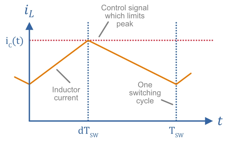
Peak Current Mode Control
Peak Current Mode Control (PCMC) is a specific type of current mode control which senses the peak current flowing through the inductor. The peak current through the inductor (and consequentially, the switch) is limited by a control signal which in turn is generated by amplifying the difference between the output voltage feedback and the reference voltage .
The below diagram shows what this looks like during continuous conduction:
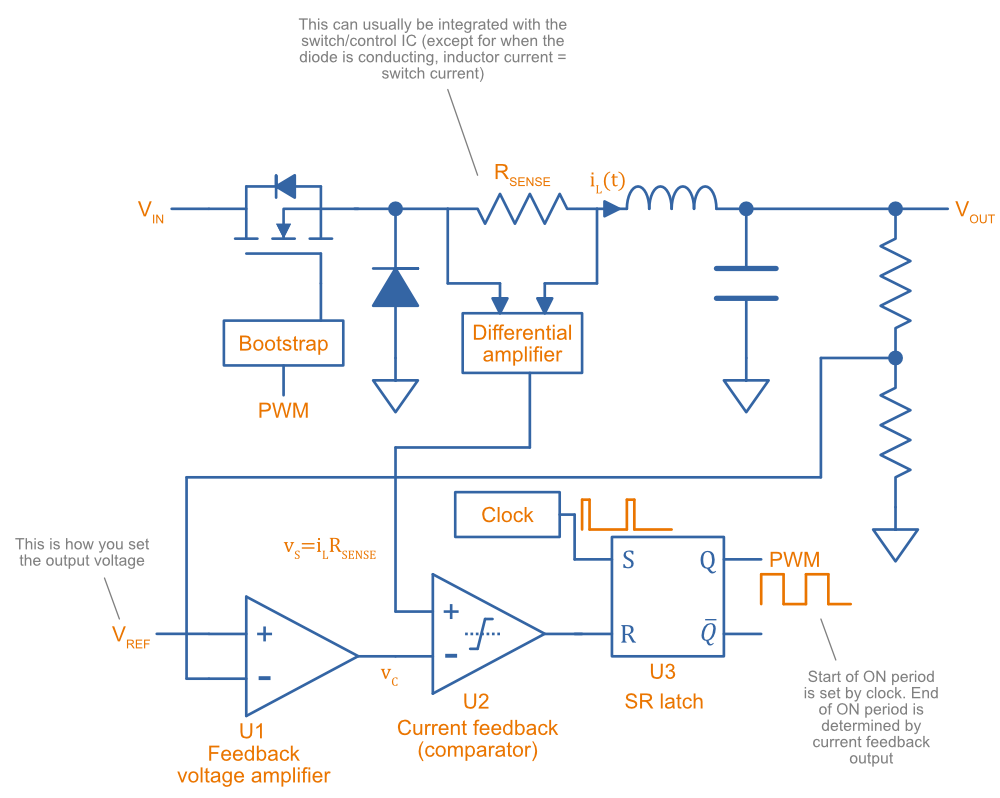
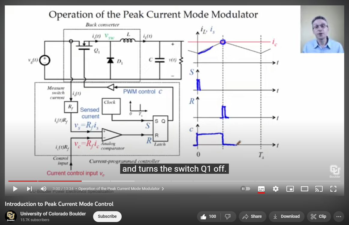
The following diagram shows the basic components of peak current mode control for a buck converter:
One benefit from controlling the peak current is that we can easily limit the maximum current through the inductor by limiting the maximum value that the control signal can ever be. We might want to do this to make sure the inductor current never exceeds it’s maximum rating (usually the minimum of it’s saturation current or rated current).
How Does This Circuit Work?
- The feedback voltage from the output resistor divider is compared to . The difference is amplified by the voltage feedback op-amp and fed into the comparator. This is compared with a voltage proportional to the inductor current.
- At the beginning of a cycle, a short clock pulse sets the output of the SR latch. This turns on the main switch (usually a MOSFET) and the current through the inductor begins rising.
- The inductor current continues to rise until the the voltage at the terminal of becomes greater than the voltage output from . At this point the comparator output goes HIGH and resets the SR latch. Thus the ON part of the cycle finishes, and the switch is turned OFF until another clock pulse arrives at the beginning of the next switching cycle.
Bootstrap/MOSFET drive circuitry is usually needed between the SR latch and the MOSFET to:
- Provide enough current to switch the MOSFET quickly.
- If a N-channel MOSFET is used, a charge-pump is needed to provided a voltage rail above to drive the gate when turning it on.
Many off-the-shelf ICs will contain both the switch and the current-sensing directly in the IC, removing the need for a separate and associated differential amplifier to measure the current.
Peak current-mode control can experience subharmonic (a.k.a. sub-cycle2) oscillation when the duty cycle increases over 50%. Slope compensation (ramp compensation) is usually added to address this issue1. Slope compensation decreases the peak current limit as the duty cycle increases, with the aim of maintaining the same average current with increasing duty cycles2.
Noise Issues and Blanking Intervals
Because the switching action causes noise, and the current-measuring voltage signal is usually low (because low-valued resistors () are used to keep power dissipation down), current mode control has a high susceptibility to noise and voltage transients3 4. The switching action can cause ringing in the voltage measurement of the current at the point of turn on. This ringing can cause the measured signal to go over the control threshold and prematurely turn the switch OFF, as shown in the below diagram:
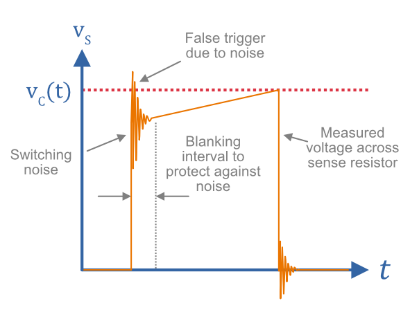
One way to compensate for this is to add in a blanking interval. This is a short interval that begins at switch turn-on in which the output of the current feedback comparator is ignored4. This improves the current mode controls noise immunity.
Further Reading
The YouTube video Introduction to Peak Current Mode Control by the University of Colorado Bolder is a great visual explanation of how current-mode control works in SMPS4.
If you want to get right into the control theory of current-mode control, the Texas Instruments Understanding and Applying Current-Mode Control Theory is a recommended read5.
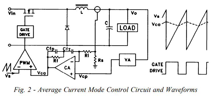
Average current mode control (as opposed to the more common peak mode control) is explained in depth in Unitrode’s Application Note “Average Current Mode Control of Switching Power Supplies” by Lloyd Dixon6.
Footnotes
-
SW Lee (2014, Mar). SLVA636 - Practical Feedback Loop Analysis for Current-Mode Boost Converter [Application Report]. Texas Instruments. Retrieved 2023-06-19, from https://www.ti.com/lit/an/slva636/slva636.pdf. ↩ ↩2 ↩3 ↩4
-
Mirochip. Introduction to SMPS Control Techniques [Webinar as PDF]. Retrieved 2023-06-20, from https://www.microchip.com/stellent/groups/sitecomm_sg/documents/training_tutorials/en527885.pdf. ↩ ↩2 ↩3
-
Texas Instruments (2020, Dec). Current Mode Control in Switching Power Supplies [Application Brief]. Retrieved 2023-06-18, from https://www.ti.com/lit/an/sboa187e/sboa187e.pdf. ↩ ↩2 ↩3
-
University of Colorado Bolder (2020, Aug 7). Introduction to Peak Current Mode Control [Video]. YouTube. Retrieved 2023-06-18, from https://www.youtube.com/watch?v=3tTSMDEyVKc. ↩ ↩2 ↩3 ↩4
-
Texas Instruments (2007, Oct 31). Understanding and Applying Current-Mode Control Theory. Retrieved 2023-06-18, from https://www.ti.com/lit/an/snva555/snva555.pdf. ↩
-
Lloyd Dixon. Average Current Mode Control of Switching Power Supplies [Application Note]. Retrieved 2023-06-20, from https://www.ti.com/lit/an/slua079/slua079.pdf. ↩ ↩2