Controlling LED Brightness Using PWM

This page covers how to control the brightness of a single LED using PWM with firmware running on a microcontroller. We’ll assume you want to vary the brightness, and to do so in a smooth manner. We’ll start off by covering the basics with linear duty-cycle control and then move onto more advanced ways that take into account the human eye’s non-linear response to light intensity.
Fixed Brightness
If all you need is a fixed brightness, rather than having to consume a PWM peripheral in the microcontroller and add to the firmware complexity, you could just set the LED current by choosing the appropriate resistor. This will impart a slight colour change (LED colour changes slightly with current), but won’t be noticeable for most use cases.
The below image shows how you can do this. The MOSFET U1 has been added so that the LED can be driven with currents higher than the maximum specified by the microcontroller’s GPIO pin (which is normally in the 1-20mA range, check the datasheet of the MCU!). You could omit this MOSFET (and the resistor R2) and just drive the LED directly if the MCU can supply the required current directly.
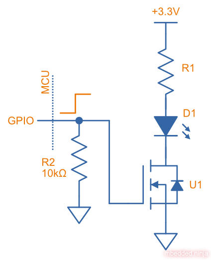
There is nothing that exciting about this though! So let’s move on to how to vary the brightness…
Varying the Intensity
The easiest way of dynamically varying the brightness of an LED is to use pulse-width modulation (PWM). PWM is available on almost all MCUs. The below image shows the circuit. It does not change much from above, you just need to make sure you connect to a pin which is PWM capable (some MCUs like the Nordic nRF52 family let you route the PWM channels to any GPIO).
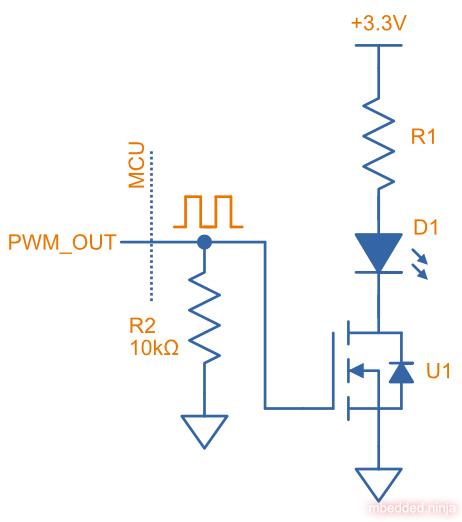
PWM is a digital signal with a fixed frequency but an adjustable on-time (hence the “width modulation”). The duty cycle is the time the signal is on compared to the total period of the signal.
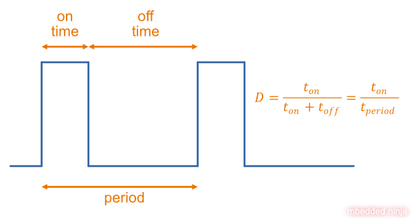
If the PWM period was 1s (a frequency of 1Hz) and the duty cycle 50%, we would see the LED “blink”. However — if the PWM frequency is fast enough (e.g. 1kHz), we do not see any flicker due to persistence of vision. Instead, because of the “averaging” that occurs in our eyes, a LED driven at 20mA for 50% of the time (50% PWM duty cycle) looks the same as driving the LED continuously at 10mA (ignoring the slight colour change due to changing current). This is great news! It means we can easily drive our LED using digital on/off signals, and don’t have to implement costly and potentially energy inefficient analog current sources/sinks.
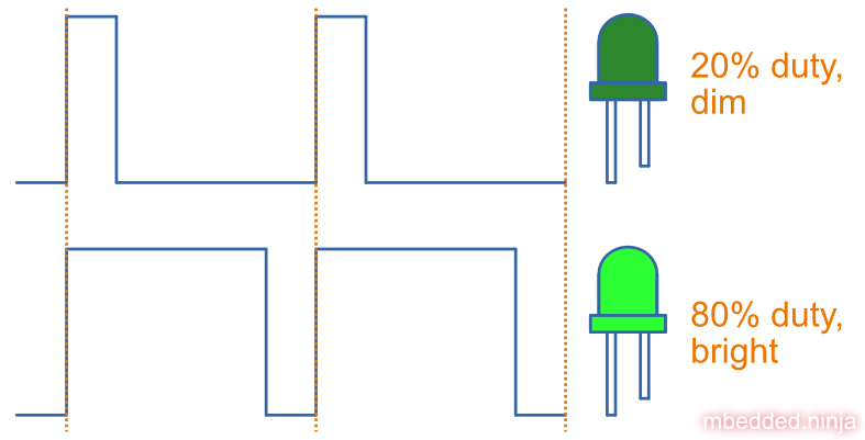
So we can vary the duty cycle of the PWM to vary the light output (radiant flux) of the LED. 0% duty cycle would make the LED turn off, and 100% duty cycle would be full brightness. The video below shows an LED being faded from 0% intensity to 100% intensity in this manner:
The PWM frequency is (a period of ). There are 256 steps from 0% to 100% duty cycle, and the duration between step changes is (thus the total time to go from 0% to 100% is ). All this was run on a Nordic nRF52 development board, and the firmware can be found at https://github.com/gbmhunter/blog-controlling-led-brightness-using-pwm.
The nice thing is that radiant flux (and intensity) varies very linearly with duty cycle. This is great if humans are not involved (e.g. agricultural grow LEDs for plants). However if you look at an LED whose duty cycle is linearly varied from 0% to 100%, you won’t perceive a uniform change in brightness! You can see this in the above video, it seems to go from off to quite bright really early in the cycle.
Adjusting For Our Eyes (Perceived Brightness)
Our eyes work over a huge range of brightness, and to do that they are not linearly sensitive to light output. Our eyes are far more sensitive to changes when the intensity is low compared to when the intensity is high. This human perception of brightness follows somewhat of a logarithmic response (similar to our hearing!).
If we wanted to set the brightness to half, this then means we need to set the PWM duty cycle to something less than 50%. Furthermore, if we wanted to fade the LED from off to full brightness, we can’t just linearly change the duty cycle. What we need is a function which maps perceived brightness to a PWM duty cycle. There are two functions that we will discuss below.
The CIE Lightness Method
The Equations
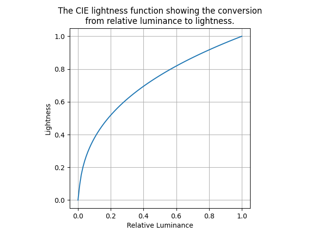
An accurate way to take into account perceived brightness is to use the CIE lightness formula. CIELAB represents lightness with the symbol 2 (not to be confused with just which is used for luminance). Lightness adjusts for the eyes non-linear response to changes in intensity. The CIELAB lightness equation is:
where:
is the lightness value in the range .
is the Y tristimulus value of the colour.
is the Y tristimulus value of the reference white point.
is called the relative luminance. This is just a number that goes from 0 to 1. The trick here is that we can assume the relative luminance is proportional to the duty cycle of the LED (and intensity). Thus is essentially our duty cycle as a number from 0 to 1.
One restriction the equation has is that . In 1976 an article by Hartmut Pauli extended the formula to remove this limitation.2 It extends the formula down to (which maps to ) and is tangent to the formula above where the two curves meet. This gives the following formula:
Great! Now we have a formula which can convert a duty cycle () in the range to a lightness value in the range . This combined 2-part formula is shown below:
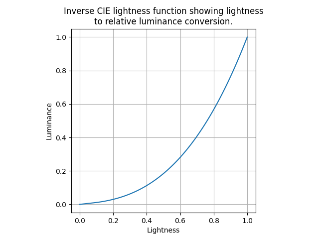
To make use of this in our firmware we first need to invert it — we need to go the other way and convert a lightness to a duty cycle. This is easy to do by rearranging the formula:
The inverted formula gives the relationship shown below:
Look-up Tables (LUTs)
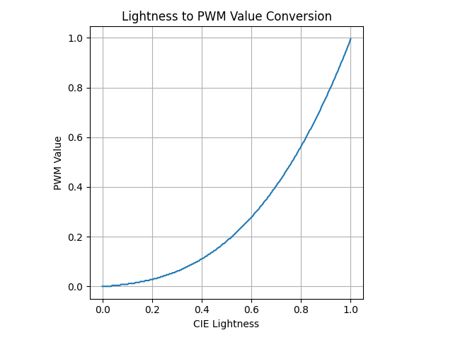
We could now use this formula in our firmware to convert a lightness value to a PWM duty cycle. However, given the power and divide operations in it, this is a bit computationally expensive. In most cases a better way is to use a look-up table (LUT). The index of the LUT is the lightness value, and the value at that index is the PWM duty cycle.
Below is an example LUT in C which takes a lightness value as an integer in the range (8-bit) and gives you the corresponding PWM duty cycle as an integer in the range . Values have be rounded DOWN to the nearest integer (i.e. float is cast to an int).
const uint8_t CIE_LIGHTNESS_TO_PWM_LUT_256_IN_8BIT_OUT_ROUND_DOWN[] = { 0, 0, 0, 0, 0, 0, 0, 0, 0, 0, 1, 1, 1, 1, 1, 1, 1, 1, 1, 2, 2, 2, 2, 2, 2, 2, 2, 3, 3, 3, 3, 3, 3, 3, 4, 4, 4, 4, 4, 5, 5, 5, 5, 5, 6, 6, 6, 6, 6, 7, 7, 7, 7, 8, 8, 8, 8, 9, 9, 9, 10, 10, 10, 11, 11, 11, 12, 12, 12, 13, 13, 13, 14, 14, 14, 15, 15, 16, 16, 16, 17, 17, 18, 18, 19, 19, 20, 20, 21, 21, 22, 22, 23, 23, 24, 24, 25, 25, 26, 26, 27, 28, 28, 29, 29, 30, 31, 31, 32, 33, 33, 34, 35, 35, 36, 37, 37, 38, 39, 40, 40, 41, 42, 43, 44, 44, 45, 46, 47, 48, 49, 49, 50, 51, 52, 53, 54, 55, 56, 57, 58, 59, 60, 61, 62, 63, 64, 65, 66, 67, 68, 69, 70, 71, 72, 73, 75, 76, 77, 78, 79, 80, 82, 83, 84, 85, 87, 88, 89, 90, 92, 93, 94, 96, 97, 99, 100, 101, 103, 104, 106, 107, 108, 110, 111, 113, 114, 116, 118, 119, 121, 122, 124, 125, 127, 129, 130, 132, 134, 135, 137, 139, 141, 142, 144, 146, 148, 149, 151, 153, 155, 157, 159, 161, 162, 164, 166, 168, 170, 172, 174, 176, 178, 180, 182, 185, 187, 189, 191, 193, 195, 197, 200, 202, 204, 206, 208, 211, 213, 215, 218, 220, 222, 225, 227, 230, 232, 234, 237, 239, 242, 244, 247, 249, 252, 255,};The video below shows an LED (on the right) being faded from off to full brightness using the CIE lightness method with the 256in/256out LUT above. The LED on the left is the linearly controlled duty cycle LED from above for comparison:
Hopefully, the CIE lightness LED looks like a smoother fade to the eye than the linear one. Admittedly, the difference between these two LEDs is not great. I’ve noticed that linear duty cycle control on LEDs with a much brighter output looks really bad before, so perhaps the fact that both of these LEDs are low power is somewhat hiding the differences.
The PWM frequency and step duration is the same as the first example above.
The Python code I wrote to create these LUTs is below if you want to modify it and create your own LUTs. It should run on most versions of Python 3, and the only 3rd party dependency is numpy.
from pathlib import Path
import numpy as np
SCRIPT_DIR = Path(__file__).parent
def main():    # Create LUTs    # ==============================
    # 256 values in, 8-bit out    createCieLightnessToPwmDutyLut(256, 8, 'cie-lightness-to-pwm-256-in-8bit-out-lut.h')
    # 256 values in, 10-bit out    createCieLightnessToPwmDutyLut(256, 10, 'cie-lightness-to-pwm-256-in-10bit-out-lut.h')
def cieLightnessToRelativeLuminance(lightness):    """    Convert a lightness value to a luminance value.
    Equation from https://www.photonstophotos.net/GeneralTopics/Exposure/Psychometric_Lightness_and_Gamma.htm.
    :param lightness: The lightness value to convert in the range [0, 1].    :return: The luminance value in the range [0, 1].    """
    # Equation from https://www.photonstophotos.net/GeneralTopics/Exposure/Psychometric_Lightness_and_Gamma.htm    lightness *= 100 # Convert to [0, 100] to work with the equation    if lightness <= 8:        return lightness / 903.3    else:        return ((lightness + 16) / 116) ** 3
def createCieLightnessToPwmDutyLut(numLightnessValues, pwmBits, filename: str):    numPwmValues = 2**pwmBits
    # Create an array of lightness values from 0 to 1    lightnessValues = np.linspace(0, 1, numLightnessValues)
    # Calculate PWM values for input lightness values    # The "+ 0.5" is so that we round to the nearest integer rather than always rounding down.    pwmValues = [int(cieLightnessToRelativeLuminance(lightness) * (numPwmValues - 1) + 0.5) for lightness in lightnessValues]
    # Calculate datatype that can hold the number of bits    if pwmBits <= 8:        datatype = 'uint8_t'    elif pwmBits <= 16:        datatype = 'uint16_t'    elif pwmBits <= 32:        datatype = 'uint32_t'    else:        raise ValueError('Num. of bits for PWM too large.')
    # Create and write to file    with open(SCRIPT_DIR / filename, 'w') as file:        file.write(f'const {datatype} CIE_LIGHTNESS_TO_PWM_LUT_{numLightnessValues}_IN_{pwmBits}BIT_OUT[] = {{')        for idx, pwmValue in enumerate(pwmValues):            # Insert a new line every 16 values            if idx % 16 == 0:                file.write('\n')            file.write(f'{pwmValue:5d},')        file.write('\n};\n')
Below is the same LUT, but with the output rounded to the closest integer (i.e. add +0.5, then cast the float to an int). This might give better results? At first I thought so, but then I realized that there will be less 0’s, more 1’s, and then a monotonic decrease in frequency of 2’s, 3’s, etc. Because of this skewing of the 0’s I’m not sure it’s the right approach.
const uint8_t CIE_LIGHTNESS_TO_PWM_LUT_256_IN_8BIT_OUT_ROUND_NEAREST[] = { 0, 0, 0, 0, 0, 1, 1, 1, 1, 1, 1, 1, 1, 1, 2, 2, 2, 2, 2, 2, 2, 2, 2, 3, 3, 3, 3, 3, 3, 3, 3, 4, 4, 4, 4, 4, 4, 5, 5, 5, 5, 5, 6, 6, 6, 6, 6, 7, 7, 7, 7, 8, 8, 8, 8, 9, 9, 9, 10, 10, 10, 10, 11, 11, 11, 12, 12, 12, 13, 13, 13, 14, 14, 15, 15, 15, 16, 16, 17, 17, 17, 18, 18, 19, 19, 20, 20, 21, 21, 22, 22, 23, 23, 24, 24, 25, 25, 26, 26, 27, 28, 28, 29, 29, 30, 31, 31, 32, 32, 33, 34, 34, 35, 36, 37, 37, 38, 39, 39, 40, 41, 42, 43, 43, 44, 45, 46, 47, 47, 48, 49, 50, 51, 52, 53, 54, 54, 55, 56, 57, 58, 59, 60, 61, 62, 63, 64, 65, 66, 67, 68, 70, 71, 72, 73, 74, 75, 76, 77, 79, 80, 81, 82, 83, 85, 86, 87, 88, 90, 91, 92, 94, 95, 96, 98, 99, 100, 102, 103, 105, 106, 108, 109, 110, 112, 113, 115, 116, 118, 120, 121, 123, 124, 126, 128, 129, 131, 132, 134, 136, 138, 139, 141, 143, 145, 146, 148, 150, 152, 154, 155, 157, 159, 161, 163, 165, 167, 169, 171, 173, 175, 177, 179, 181, 183, 185, 187, 189, 191, 193, 196, 198, 200, 202, 204, 207, 209, 211, 214, 216, 218, 220, 223, 225, 228, 230, 232, 235, 237, 240, 242, 245, 247, 250, 252, 255,};Quantization
The 256 in/256 out LUT above might be fine for basic applications (e.g. indicator LED on a PCB). In other applications you might notice jerkyness, and so you have to consider the effects of quantization and the resolution you are getting. If you had an 8-bit PWM, with only 256 discrete settings for the duty cycle, your smallest non-off value (setting the duty cycle to 0x01) is 0.39% of the maximum brightness! You can see this by looking at the “round down” LUT above, the first 10 lightness values all map to a PWM duty cycle of 0.
If we use a 10-bit PWM, our LUT would look like this:
const uint16_t CIE_LIGHTNESS_TO_PWM_LUT_256_IN_10BIT_OUT[] = { 0, 0, 0, 1, 1, 2, 2, 3, 3, 3, 4, 4, 5, 5, 6, 6, 7, 7, 7, 8, 8, 9, 9, 10, 10, 11, 11, 12, 12, 13, 14, 14, 15, 15, 16, 17, 17, 18, 19, 20, 20, 21, 22, 23, 24, 24, 25, 26, 27, 28, 29, 30, 31, 32, 33, 34, 35, 36, 38, 39, 40, 41, 42, 44, 45, 46, 48, 49, 50, 52, 53, 55, 56, 58, 59, 61, 62, 64, 66, 67, 69, 71, 73, 74, 76, 78, 80, 82, 84, 86, 88, 90, 92, 94, 96, 98, 101, 103, 105, 107, 110, 112, 115, 117, 120, 122, 125, 127, 130, 132, 135, 138, 141, 143, 146, 149, 152, 155, 158, 161, 164, 167, 170, 173, 176, 180, 183, 186, 190, 193, 196, 200, 203, 207, 211, 214, 218, 222, 225, 229, 233, 237, 241, 245, 249, 253, 257, 261, 266, 270, 274, 278, 283, 287, 292, 296, 301, 305, 310, 315, 320, 324, 329, 334, 339, 344, 349, 354, 359, 365, 370, 375, 380, 386, 391, 397, 402, 408, 414, 419, 425, 431, 437, 443, 449, 455, 461, 467, 473, 479, 485, 492, 498, 505, 511, 518, 524, 531, 538, 545, 551, 558, 565, 572, 579, 586, 594, 601, 608, 616, 623, 631, 638, 646, 653, 661, 669, 677, 685, 693, 701, 709, 717, 725, 733, 742, 750, 759, 767, 776, 784, 793, 802, 811, 820, 829, 838, 847, 856, 865, 875, 884, 893, 903, 913, 922, 932, 942, 952, 962, 971, 982, 992, 1002, 1012, 1023,};See how there are far fewer identical outputs at the start of the LUT when using a 10-bit output? Only the first three lightness values map to a 10-bit PWM of 0, rather than the first 10 when using an 8-bit PWM.
Once you run out of PWM resolution, for even smoother control, you can use temporal dithering to artificially increase the resolution of the PWM. This is where you vary the duty cycle around the desired value to give the appearance of a higher resolution PWM.3
Gamma Correction
Instead of the CIE lightness function for linearizing perceived brightness, some people use the gamma function instead. The gamma function was designed to convert from a CRT voltage to the luminance.4 It just happens that the Gamma function is very similar to the CIE lightness formula above and gives you “good enough” results in many cases.
The gamma equation is:
where:
is the intensity
is the applied voltage
is the gamma value, and is usually set at 2.2.
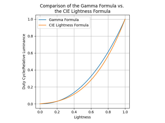
When using this for controlling LED brightness, is no longer voltage but the lightness value (input), and is the PWM duty cycle (output). Thus it becomes (the does not stand for multiplication, it’s part of the lightness symbol):
The below graph shows the gamma correction function with , plotted alongside the CIE lightness function. Note how they are very similar!
Just like with the CIE lightness function, you could create a LUT using the gamma correction function instead. Given there is no computational difference between the two (once the LUT is created), I recommend using the CIE lightness function which is likely to be that little bit more “correct”.
You might find some strong words online against using Gamma correction for LED “brightness” control, suggesting how it’s not being used for it’s intended purpose:
These power functions, with a gamma of 2.2, are frequently used to map between linear and perceptual values. Although the “gamma function” is commonly used it is arguable that CIE Lightness is the more precise formulation; and in fact CIE Lightness is the formula use for L in the CIE Lab color model rather than a gamma function5.
The gamma correction is used to correct non-linear relationship between applied voltage to CRT and luminance of CRT. It is nothing to do with human perception. — Peter Jakobs, LED Shield4.
Further Reading
An alternative to PWM for controlling LEDs is to use constant-current drivers or sinks. Rather than digitally switch the LED on and off really quickly, this technique allows you to change the current going through the LED(s). It’s generally a more expensive and complex solution, but can be a good choice in some situations, especially if you need a current-regulated SMPS anyway to power a string of LEDs.
The CodeInsecurity “The problem with driving LEDs with PWM” blog post3 is a good read. It explains temporal dithering to artificially increasing the resolution of the PWM.
The code used to generate the PWM examples on this page can be found at https://github.com/gbmhunter/blog-controlling-led-brightness-using-pwm.
Footnotes
-
Wikipedia (2024, Feb 1). Flicker fusion threshold. Retrieved 2024-04-04, from https://en.wikipedia.org/wiki/Flicker_fusion_threshold. ↩
-
Wikipedia (2024, Feb 10). Lightness. Retrieved 2024-04-03, from https://en.wikipedia.org/wiki/Lightness. ↩ ↩2
-
Graham Sutherland (2023, Jul 17). The problem with driving LEDs with PWM. CODEINSECURITY. Retrieved 2024-04-04, from https://codeinsecurity.wordpress.com/2023/07/17/the-problem-with-driving-leds-with-pwm/. ↩ ↩2
-
Peter Jakobs (2012, Nov 13). LED Brightness to your eye, Gamma correction – No!. LED Shield. Retrieved 2024-04-03, from https://ledshield.wordpress.com/2012/11/13/led-brightness-to-your-eye-gamma-correction-no/. ↩ ↩2
-
Bill Claff (2005, Mar 26). Psychometric Lightness and Gamma. photonstophotos.net. Retrieved 2024-04-03, from https://www.photonstophotos.net/GeneralTopics/Exposure/Psychometric_Lightness_and_Gamma.htm. ↩