Inverting Buck-Boost Converters

Inverting Buck-Boost Converters
An inverting buck-boost is a type of switch-mode power supply (SMPS) that converts an input voltage into a higher or lower output voltage. It is given the name inverting because it generates a negative output voltage.

Output Voltage
The output voltage for an ideal inverting buck-boost is purely determined by the input voltage and the duty cycle , as given in the following equation:
To give you an idea of how varying the duty cycle can produce either a higher or lower output voltage, see the below image which shows how the output voltage can vary from a small fraction of to many times larger than , and they are equal when the duty cycle is set at 50%.
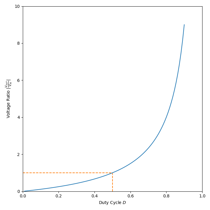
As the duty cycle approaches 100%, the ideal output voltage approaches infinity! In practice, non-idealities and component absolute maximums limit the output voltage to something in the range of 10x the input voltage.