Isolated Switch Mode Power Supplies

For regular non-isolated buck, boost, regulators, SEPIC and Ćuk regulators see the Switch Mode Power Supplies (SMPS) page.
Isolated SMPS topologies:
| Name | Advantages |
|---|---|
| Flyback | Requires no inductor (uses the transformer). Simple. Low cost. |
| Flybuck | Higher freq. than flyback (= smaller components/better efficiency). |
| Forward |
Flyback Converters
A flyback converter is a type of isolated power converter. It can be thought of as a buck-boost converter with the inductor split to form a transformer. The basic schematic is shown below:

Flyback converters are unique in the fact that they use the transformer as both a transformer (to provide voltage/current conversion and isolation) and inductor (for storage of energy in its magnetic field). All other isolating SMPSs only use the transformer for voltage/current conversion and isolation, and require a separate inductor on the secondary side for performing the buck/boost regulation. The flyback converter is the most used isolating SMPS topology.1
Principle Of Operation
-
Switch closes. The primary of the transformer is connected directly to the input. The current ramps up linearly in the transformer, storing energy in its magnetic field. Since the voltage on the secondary is negative (note the polarity dots on the windings), diode is reverse biased and does not conduct, leaving to supply energy to the load (which it does from energy stored in the previous cycle).
-
Switch opens. The primary current drops (very rapidly). Suddenly, the secondary voltage becomes positive, and conducts. This supplies energy to both and the load.
The output voltage is given below.
where:
is the windings ratio from primary to secondary,
is the duty cycle, and varies from to . It is defined as:
Feedback
Without feedback, regulation for a flyback converter can be as good as 5-10% (assuming the input voltage is known and constant). If you need tighter precision of the output voltage, or if the input voltage varies wildly, you will need to add feedback.
The TL431 precision shunt voltage reference in tandem with an optocoupler is a popular way of providing feedback from the secondary side back to a flyback converter. As shown below, its REF pin is connected via resistor divider to , and it sinks as much current through the optocoupler’s LED to keep at , hence providing just enough feedback drive to regulate the output voltage.

Flyback converters are used extensively in Power over Ethernet (PoE) applications.
Controllers
- LM3481
Flybuck Converters
TODO: Add info here.
Forward Converters
TODO: Add info here.
Modules
Rather than designing the circuitry yourself, you can purchase isolated SMPS modules from a number of suppliers.
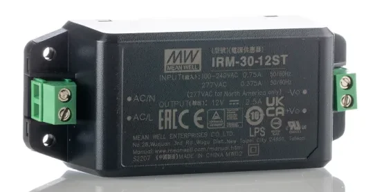
For example, the Mean Well IRM-30-12ST shown below is a 30W 85-264VAC input, 12V output isolated SMPS module. There is also a PCB variant of this module which has bottom side through-hole pins rather than the terminal blocks shown.
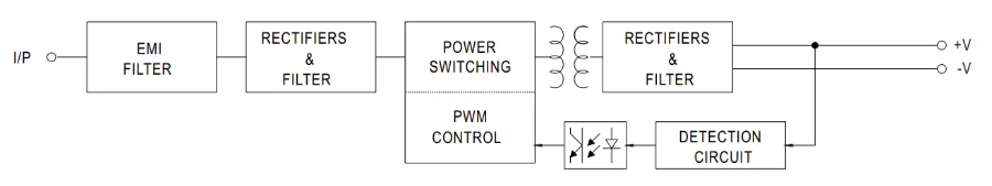
The high-level internal block diagram of the Mean Well IRM-30-12ST is shown below.
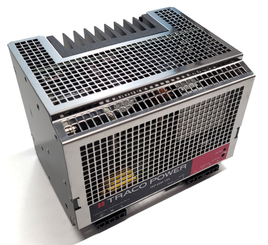
DIN Mounted Isolated SMPS
You can purchase DIN mounted isolated SMPS modules from a number of suppliers. These are typically used in industrial applications such as in control panels/cabinets.
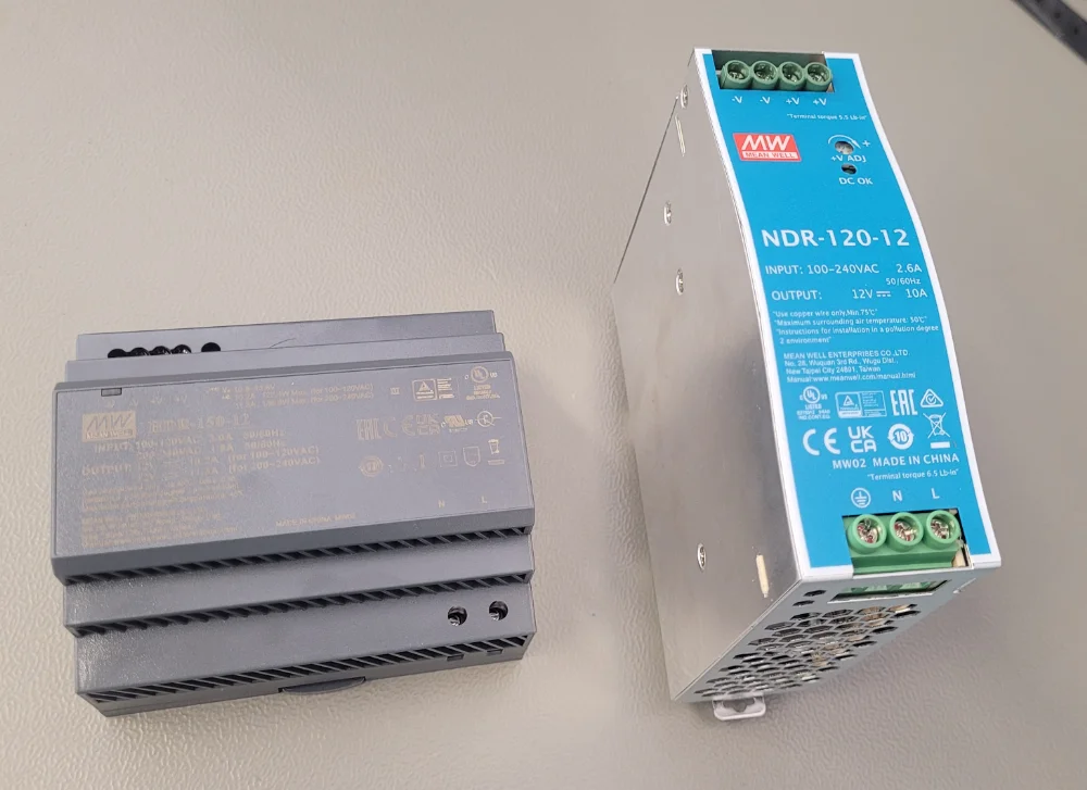
The photo below shows two Mean Well DIN mounted isolated SMPS modules. The one on the left is a wide but short HDR-150-12 (12V, 150W) and the one on the right is a narrow but tall NDR-120-12 (12V, 120W). The NDR-120-12 doesn’t take up much horizontal space on the DIN rail, but requires a much larger height clearance (about 120 mm upwards from the DIN rail), making it more suitable to large control cabinets rather than polycarbonate enclosures.
Footnotes
-
Lee, S.W. (2020, May). Practical Feedback Loop Design Considerations for Flyback Converter Using UCC28740. Texas Instruments. Retrieved 2021-08-27, from https://www.ti.com/lit/an/sluaa66/sluaa66.pdf. ↩
-
RS Components. MEAN WELL Switching Power Supply, IRM-30-12ST, 12V dc, 2.5A, 30W, 1 Output, 85 → 264V ac Input Voltage [product page]. Retrieved 2024-12-05, from https://nz.rs-online.com/web/p/switching-power-supplies/1358951. ↩ ↩2