Resistors

Resistors are a passive electronic components that restrict the flow of current when a voltage is applied across them. They dissipate the energy lost as heat. Given their simplicity, usefulness and low price of manufacture, they are typically the most commonly used electronic component in any circuit design.
The mechanical equivalent of a resistor is friction. The larger the resistance, the larger the friction. This is when using the force-voltage equivalence.

Resistors are used for a huge number of purposes, including:
- Resistor dividers: To produce an output voltage that is a fixed percentage of the input voltage.
- Voltage/current biasing: e.g. transistor amplifiers
- Current limiting: Power an LED from a fixed voltage rail.
- Op-amp gain/feedback configuration: Resistors (along with the occasional capacitor) are used to set the gain/feedback of op-amps.
- Impedance matching
- Current measuring: Resistors convert a current into a voltage, which is easily measurable by op-amps/ADCs/etc.
- GPIO/communication bus pull-up/pull-downs: To drive nets into passive states, for example to keep the gate tied to source so it’s always OFF unless driven on. Also to drive communication bus lines into passive states, especially buses that use arbitration (e.g. I2C, CAN bus).
Child Pages
Schematic Symbols
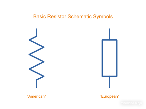
The most commonly-used resistor schematic symbols are shown in This is a placeholder for the reference: schematic-symbols-amer-euro-resistors. I prefer the American-style resistor over the European purely because there are already many “box-like” schematic symbols used for other components (e.g. fuses, ICs), and so the squiggle makes a resistor more distinguishable (given my distaste for the American imperial system, I never thought I would ever say that!). The American style is used through-out the rest of this website.
See the Potentiometers And Rheostats page for more schematic symbols related to resistors.
Ohm’s Law
The fundamental relationship between voltage, current and resistance is given by Ohm’s law:
where:
is the voltage across the resistor, in
is the current through the resistor, in
is the resistance of the resistor, in
Ohm’s Law Calculator
Use the calculator below to solve for any one of voltage, current or resistance given the other two. Inputs accept metric prefixes (e.g. 12, 1m, 4k7).
Resistors In Series And In Parallel
The behaviour of resistors when connected together in series and in parallel is exactly the same behaviour inductors exhibit, and exactly the opposite behaviour of what capacitors exhibit.
Resistors In Parallel
When two resistors are connected in parallel, the equivalent total resistance follows the inverse law:
It is usually easier to remember this equation as:
This can be generalized to number of resistors in parallel:
This relationship is shown in in the below image.
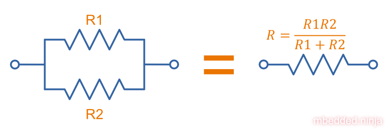
One quick equation you can remember that works as long as you only have two resistors in parallel is:
Use the calculator below to find the total resistance of two or more resistors in parallel. Each input accepts metric prefixes (e.g. 10k, 2M2, 470R).
Resistors In Series
When two resistors are connected in series, the total equivalent resistance is equal to the sum of individual resistances.
This is shown in the below image.

This can be generalized to number of resistors in series simply as:
Use the calculator below to find the total resistance of two or more resistors in series. Each input accepts metric prefixes (e.g. 10k, 2M2, 470R).
Network Analysis
Sometimes you have to think carefully about the circuit connections to determine whether resistors are in series or parallel. For example, what is the equivalent resistance between points and in the circuit shown in This is a placeholder for the reference: fig-3-resistors-in-a-confusing-parallel-arrangement?
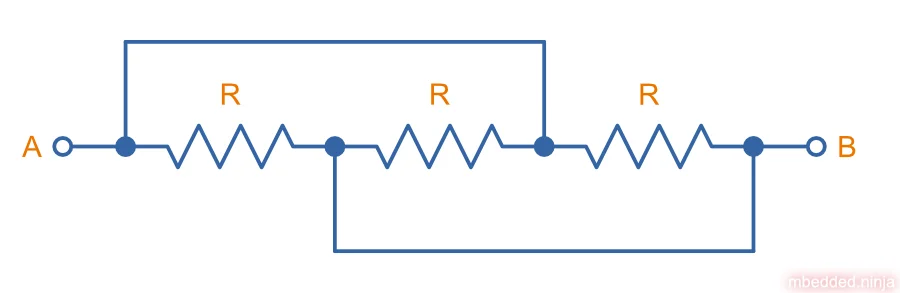
The answer is , because all of the resistors are in parallel (using This is a placeholder for the reference: eqn-resistors-in-parallel-n). This may not be obvious at first glance, but the two nodes have been highlighted in This is a placeholder for the reference: fig-3-resistors-in-a-confusing-parallel-arrangement-nodes-highlighted. It should then become pretty clear that all the resistors are in parallel. While you should never ever draw a schematic like this for a real world project/design (where the aim is to draw things as clearly as possible) it is a useful exercise to get into the habit of analysing the nodes in circuits (this sort of convoluted series/parallel arrangement question is a favourite for people writing university exams).

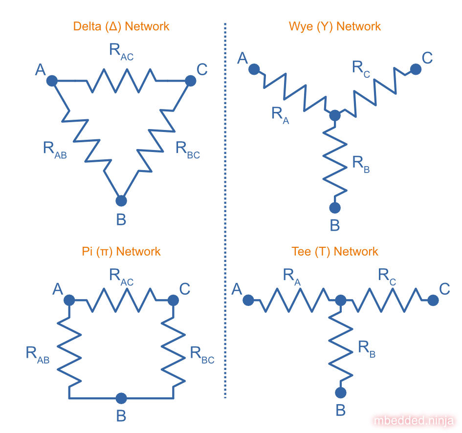
Some more complicated resistor networks can’t be solved with methodical application of parallel and series combinations alone. See the Delta-Wye Resistor Networks page for more information.
Kirchhoff’s circuit laws (KVL and KCL) are another useful tool when analysing resistor networks.
Resistor Dividers
Resistor dividers are two or more resistors in a series configuration such that at some junction in the string, the voltage is a fixed proportion of the total voltage applied to the end’s of the string. In this way, they divide the input voltage (applied across the entire string) into a smaller output voltage (measured across only part of the string).
The simplest voltage divider consists of just two resistors in series, as shown in This is a placeholder for the reference: resistor-divider-schematic.

The equation for is:
The input voltage “divides” itself across the resistors proportionally based on relative resistances. The more resistance of any one resistor, the greater amount of voltage that will drop across it. You can easily reach the above equation by applying Ohm’s law to the circuit.
During circuit design, you will encounter times when you have three knowns from the equation above but have to solve for any one of the others. Thus it has be re-arranged for every variable below for convenience (with and being able to be simplified slightly):
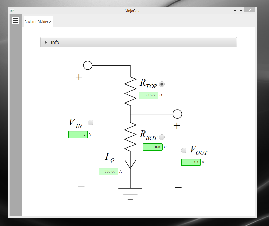
Use the calculator below to solve a resistor divider for any one parameter given the other three. Select the parameter to compute with the radio button on its row; the remaining rows become inputs. Voltage and resistance inputs both accept metric prefixes (e.g. 5V, 3.3, 10k, 2M2).
Thevenin Equivalent Circuit
The Thevenin equivalent circuit for a resistor divider is shown in This is a placeholder for the reference: resistor-divider-thevenin-equivalent-diagram. This is the equivalent circuit as looking from into the resistor divider.
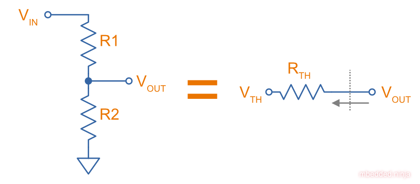
Where the Thevenin voltage is equal to the open-circuit output voltage:
and the Thevenin resistance is equal to the open-circuit output voltage divided by the short-circuit current:
The Thevenin resistance is sometimes called the output resistance or impedance . The Thevenin equivalent circuit is useful for calculating how long a capacitor attached to the output will take to charge to a certain level. It allows you to have a single resistance that you can then plug into the time constant equation . For more info on this, see the RC Charging Circuits page. It is also useful when looking at it’s frequency response. For more info on this, see the Analogue Filters page.
Note that the output impedance of a resistor divider is normally quite high, compared to other “standard” voltage sources. For this reason, you cannot normally use a resistor divider to drop the voltage and provide power to a device. This is a common mistake that people learning electronics do, when in reality you should either be using a linear regulator, a SMPS, or a transformer. Voltage dividers should normally only be used to provide a voltage to a high-impedance input (e.g. op-amp input, comparator input, microcontroller ADC input, or voltage-level translation for comms signals).
The exception to the above rule is when the two following conditions are met:
- The device will draw a small enough current that the voltage sag due to the extra current through is acceptable.
- Voltage fluctuations when the load changes are acceptable (i.e. this is not active regulation…there is no feedback).
- The current going through will not cause it to overheat.
Applications
Resistor dividers are used everywhere in circuit design! They are commonly used for:
- Scaling down a higher voltage (e.g. a 0-12V voltage rail) down to something that can be measured by an ADC (e.g. 0-2.5V).
- Biasing transistors.
- Providing the correct voltages to the inputs of op-amps.
An interesting example I have seen of a resistor divider powering a circuit was a low-power microcontroller being powered directly from a resistor-divider, diode and capacitor from mains supply (240VAC). The microcontroller only drew so met the above criteria for using a resistor divider as a power supply.
Online Calculators
NinjaCalc has a calculator that can work out voltages, resistances and currents of a resistor divider.
Tolerances
The tolerance of a resistor defines how accurately the resistor the actual resistors value is to the specified value, usually in terms of a percentage. 5% and 1% resistors are the most common. Typically the cost of a resistor goes up as the tolerance reduces, as it requires increased manufacturing precision.
5% resistors are normally fine for the most resistor jobs such as:
- Current-limiting
- ESD protection
- Pull-ups/pull-downs
- Termination resistors
1% or lower precision is usually required for:
- Resistor dividers for ADC inputs
- Op-amp gain resistors
- Current measuring resistors (0.1% precision may be needed here, and they start costing a bit!)
With the advent of SMD resistors, the difference in price between 1% and 5% resistors is so insignificant that for most purposes you can get away with using 1% tolerance resistors for everything in your circuit design.
Can I Put Resistors In Series Or Parallel For Better Tolerances?
The short answer. No. 2x 1% resistors in series is the equivalent to 1x 1% resistor.
The long answer. You will never get a worse tolerance by putting two resistors in series or parallel. BUT, you may get a better distribution of values, depending on the distribution of the original resistors. If you assume (and this might be a bad assumption) that the resistor values followed a Gaussian distribution, then the resulting distribution is a better Gaussian distribution (skinnier/smaller deviation). If the original resistors had a flat distribution, the resulting distribution is a triangle shape.
However, the distribution of resistor values could be any number of shapes. For example, the manufacturer might make heaps of 5% resistors, which are then measured. If the resistance falls within 1% of , then they are made into 1% resistors. This would leave the 5% resistor bin with a double peak, with a valley right in the middle of the distribution.
Also, correlation between resistors from the same manufacturing batch run may mean that you do not get any standard deviation improvements.
Manually Tweaking Resistance
For non-repetitive, high precision values, you can actually tweak a resistors value by grinding some of the resistor away with a metal file. This only works for the metal film style resistors. See this video as an example.
The E Series
Practically all resistors follow an E series, a scale of predefined resistances that have standardised by IEC 60063. This type of sequence is called preferred numbers. Common E series are the E12, E24, E48, E96 and E192 series. The series divides the numbers between 1 and 10 into 12, 24, 48, etc. steps. The steps are chosen so that maximum relative error between any resistance you want and the closest resistance in the series is fixed (i.e. constant).
Simply, this means that each series guarantees you will be able to find a resistor that equals the resistance you need within a fixed maximum percentage error.
| Series | Maximum Percentage Error |
|---|---|
| E6 | 20% |
| E12 | 10% |
| E24 | 5% |
| E48 | 2% |
| E96 | 1% |
| E192 | 0.5% |
The E192 series is also used for 0.25% and 0.1% error resistors.
Below are all the actual values for the common E series. They are written as initialised arrays in the C programming language, so that you can copy them and use them in code easily (some modifications may be required for other programming languages).
E6[6] = {10, 15, 22, 33, 47, 68};
E12[12] = {10, 12, 15, 18, 22, 27, 33, 39, 47, 56, 68, 82};
Note how there are two digits of precision for E6, E12, and E24 values, while 3 digits of precision for E48, E96 and E192 values. These two sets of three series share special properties with one another. E6 is every second value from the E12 series, and E12 is every second value from the E24 series. Similarly, E48 is every second value from the E96 series, and E96 is every second value from the E192 series.
The values come from the exponential number series, using the equation:
where:
= the i’th element in the series
= the total number of elements in the series
For any E-series range, this pattern is applied for every decade of resistance, e.g. between , , and so on. standard families of resistors will start at about and continue up to . For values outside of this range you generally have to find specialist products (e.g. precision current measuring resistors) and pay a little more for them.
E Series Resistance Finder
Use the interactive finder below to look up the closest preferred value (and the closest equal-or-lower / equal-or-higher value) for each E series for a given desired resistance.
4.7k, 470, 2M2, 0.1.| Series | Closest | Closest ≤ desired | Closest ≥ desired | |||
|---|---|---|---|---|---|---|
| Resistance | Error | Resistance | Error | Resistance | Error | |
| E6 | 10 kΩ | -2.913% | 10 kΩ | -2.913% | 15 kΩ | +45.631% |
| E12 | 10 kΩ | -2.913% | 10 kΩ | -2.913% | 12 kΩ | +16.505% |
| E24 | 10 kΩ | -2.913% | 10 kΩ | -2.913% | 11 kΩ | +6.796% |
| E48 | 10.5 kΩ | +1.942% | 10 kΩ | -2.913% | 10.5 kΩ | +1.942% |
| E96 | 10.2 kΩ | -0.971% | 10.2 kΩ | -0.971% | 10.5 kΩ | +1.942% |
| E192 | 10.4 kΩ | +0.971% | 10.2 kΩ | -0.971% | 10.4 kΩ | +0.971% |
See Wikipedia - Preferred Number for more information on these series.
Resistor Manufacturing Processes
Wire Wound
Wire-wound resistors are the oldest type of resistor, and are formed by coiling up a piece of wire to get a desired resistance. They are only typically used in modern times in high power applications and for things like fuses, with ratings up into the 100’s of Watts.

Given they are normally a coil of wire, they can have a significant parasitic inductance and be give off/be susceptible to magnetic fields.

Metal Film
Metal film resistors are the most popular resistor in today’s market. They have replaced [^_carbon_film, carbon film resistors] in most applications due to their cheaper cost, lower noise and smaller size. Metal film resistors can be split into two sub-categories, thick metal film and thin metal film.
Thick Metal Film
Thick film is the most common type of metal film resistor. Most 1% and 5% SMD chip package resistors (0402, 0603, etc.) use thick film technology.
Thin Metal Film
Most 0.1% SMD chip package resistors (0402, 0603, etc.) use thin film technology. Thin film resistors can be split into two sub-categories, commercial thin-film and precision thin-film.
Metal Foil
Even rarer than thick and thin film resistors, metal foil resistor technology allows the most precise resistors to be made.
Carbon Film
Carbon film resistors are formed by forming a conductive carbon film on a ceramic substrate. Carbon film resistors have been replaced in most applications by metal film resistors.
Power Resistors
Power resistors is a term used with resistors which are usually rated to dissipate 1W or more of power (without heatsinking).
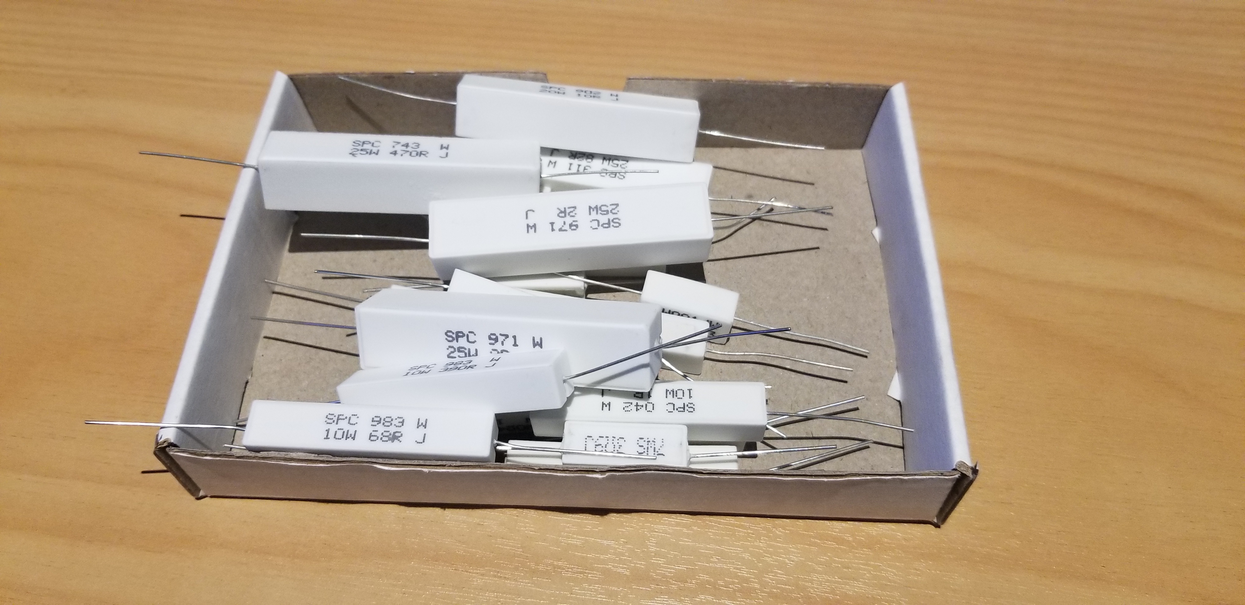
Power resistors can be used to intentionally heat things. The below image shows a common 5W resistor being used to heat a small container of oil, with a copper thermostat from a hot water cylinder being used to control the temperature.

Current-Sense Resistors
Current-sense resistors are a label given to low-valued, high precision (1% or better), and high power resistors that are good for using in current-sense circuits. Sometimes there is nothing special about these resistors (it’s purely a marketing term), other times they may have two additional terminals for Kelvin sensing. A four terminal resistor is also called an ammeter shunt. Two of the terminals are used to pass the high current, the other two are used to measure to voltage drop across the resistor. This gets rid of measurement errors due to voltage drop in the wires going to the resistor (when the sense line and high-current path are the same thing).

More information and schematics on how to make current-sense circuits can be found on the Current-Sensing page.
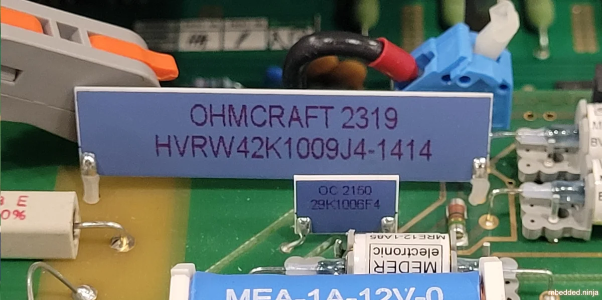
High Voltage Resistors
High voltage resistors are resistors that are rated for high voltages, typically 1000 V or more. They are used in high voltage applications, such as in power supplies. High-voltage resistors also typically have very large resistances (otherwise the current and power dissipation would be too high!), often up to 1TΩ (1 Teraohm).4
Jumpers
Most resistor series also include a 0Ω jumper resistor. Jumper resistors are great for jumping tracks when doing PCB design, as well as providing a convenient and cheap way of connecting/disconnecting certain tracks in different PCB variants.
Note that sometimes these jumper resistors can handle much less current than you expect! For example, most 0603/0805 sized SMD jumper resistors are only rated to 1-2A, even though at this current the I*R power dissipation is well below the continuous maximum (0.1-0.5W). However, some can handle some decent current, for example, the Susumu YJP1608-R001 0603 jumper resistor, which can handle 10A continuous.
Jumper resistors are not specified with a percentage tolerance as most other resistors, as this makes no sense (what is 5% of 0Ω?). Instead, they are printed as 0Ω, and a maximum resistance is given in the datasheet, which is usually in the order of 1-50mΩ.
Volume Resistance (Bulk Resistance)
Volume resistance (also known as just resistivity, electrical resistivity, or bulk resistance) has the SI units . It is a measure of how well a particular material conducts electricity, and is an intrinsic property of that material (it does not depend on how much of the material or what shape it is in). If the resistance between two conducting plates on opposite faces of a cube of material is measured to be , then the material has a volume resistivity of .
Parasitic Elements
For most day-to-day applications, resistors can just be treated as if they have a resistance. However, in high frequency circuits, there are other parasitic elements to a resistor that you must consider. Typically, the main parasitics are modelled as a extra inductor and capacitor, although the is no standard way of wiring them (depends on what literature you are reading). One popular configuration is shown in This is a placeholder for the reference: parasitic-model-of-resistor-series-rl-parallel-c.

This is a placeholder for the reference: parasitic-model-of-resistor-parallel-rc-series-l shows another model which is popular as it models the resistance in parallel with the end cap capacitance and this in series with the lead inductance6.

The below table shows resistor types and the ranges of their parasitic inductance7:
| Resistor Type | Capacitance | Inductance |
|---|---|---|
| Wirewound | 0.03-56uH | |
| Metal oxide | 3-200nH | |
| Metal foil | 0.05pF | <80nH |
| Metal film | <2nH |
Helical wirewound resistors have an especially large parasitic inductance because they are wound in a coil. They are also especially susceptible to magnetic pickup (inducing electrical noise into the circuit due to nearby magnetic fields). There are also special non-inductive wirewound resistors in where the wire is wound back and forth rather than in a coil to drastically reduce the inductance (they use the Ayrton–Perry winding technique).
Resistor Noise
Resistors add thermal (Johnson-Nyquist) noise into circuits. See the Electrical Noise page for more info.
Packages
Resistor come in many packages, from large, wire-wound power resistors that come in coils and blocks, to smaller through-hole resistors, to even smaller still SMD resistors. You can find more about resistor packages on the Component Package Database page.
Through-hole resistors use the older color code scheme (the current international standard as of 2013 is IEC 60062). Newer surface-mount resistors usually have the value printed directly on them (a three-digit number is most common, with the third digit being the multiplier).

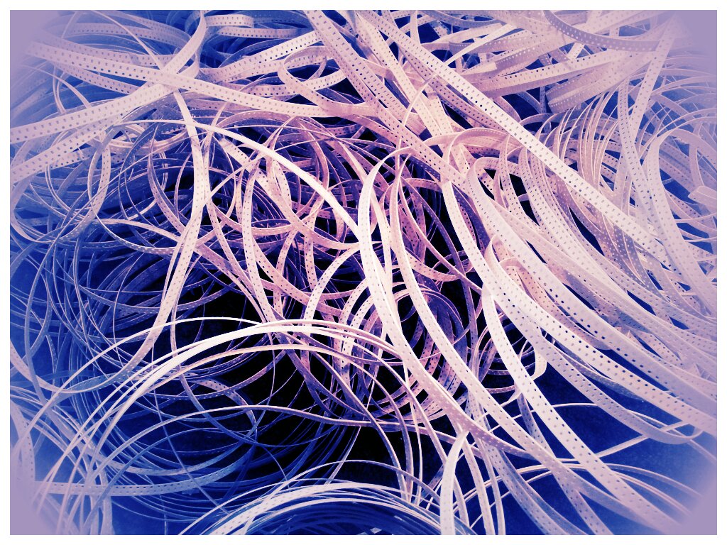
Once taken out of the tape, they don’t look like much!

This is a placeholder for the reference: reel-0603-resistor-leftovers-best was me trying to be arty-farty with the left-overs from putting about 30,000 reeled 0603 resistors into containers for prototyping with.
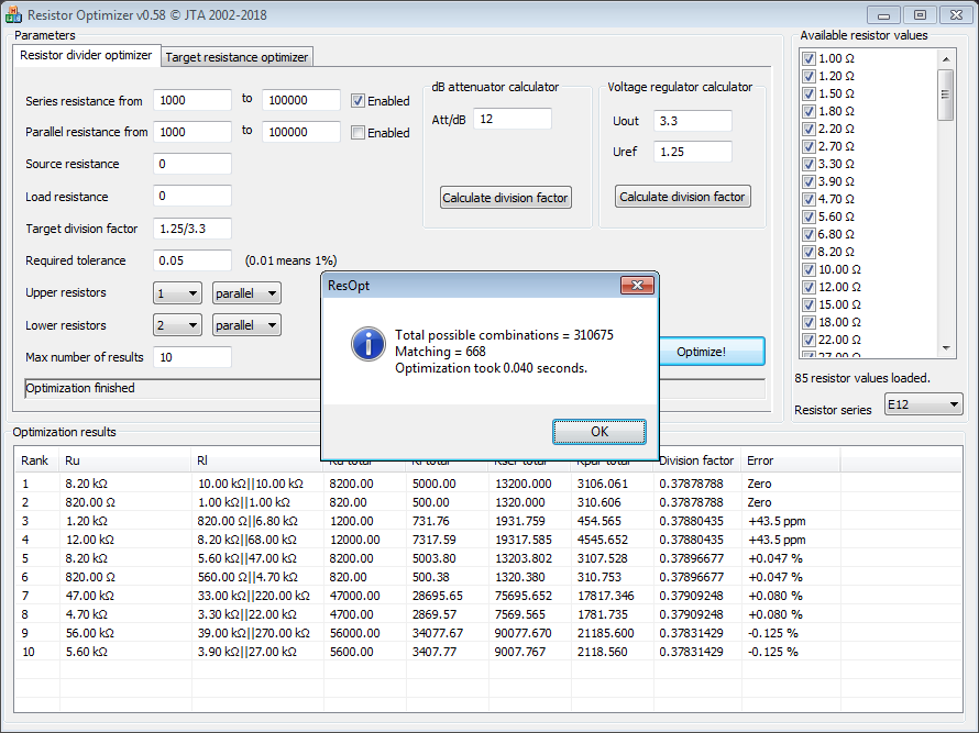
Resistor Optimizer Tool
There is a great, free tool by Janne Ahonen called Resistor Optimizer (download it here) which finds optimal values for resistor dividers and optimal values for series/parallel resistor combinations to achieve the desired total resistance. It runs on Windows (Win32 application)8.
Further Reading
For information on positive temperature coefficient resistors used as “fuses” in circuit protection applications, see the PTC Resettable Fuses page.
For info on mechanically variable resistors, see the Potentiometers and Rheostats page.
For info on digital controlled variable resistors, see the Digital Potentiometers (DPOTs) page.
The Delta-Wye Resistor Networks page shows how to transform a Delta resistor network into a Wye network, and vise versa. These networks can’t be solved with simple series and parallel combination analysis alone.
For info on how to analyze voltage drops across resistors in a circuit, see the Kirchhoff’s Circuit Laws page.
Footnotes
-
Geoffrey Hunter (2024, Feb 16). RC Charging Circuits. mbedded.ninja. Retrieved 2024-02-16, from https://blog.mbedded.ninja/electronics/circuit-design/rc-charging-circuits/. ↩
-
Yageo. Thick Film General Purpose (product page). Retrieved 2022-10-05, from https://www.yageo.com/en/Product/Index/rchip/thick_film_general_purpose. ↩
-
TT Electronics (2020, Jun). Vitreous Enamelled Wirewound Resistors: W20 Series (datasheet). Retrieved 2022-04-21, from https://www.mouser.com/datasheet/2/414/TTRB_S_A0010754439_1-2565592.pdf. ↩
-
Nicrom. Homepage. Retrieved 2025-10-09, from https://www.high-voltage-resistors.com/. ↩ ↩2
-
Ohmcraft. HVR Series - High Voltage Leaded Resistors. Retrieved 2025-10-08, from https://ohmcraft.com/wp-content/uploads/2022/02/HVR-datasheet.pdf. ↩
-
Wyatt, Kenneth (2013-10-29). Resistors aren’t resistors. EDN. Retrieved 2021-08-15, from https://www.edn.com/resistors-arent-resistors/. ↩
-
EE Power. Resistor Inductance. Retrieved 2021-08-13, from https://eepower.com/resistor-guide/resistor-fundamentals/resistor-inductance/#. ↩
-
Janne Ahonen (2018, Jun 17). Resistor optimizer (product page). Retrieved 2022-08-26, from http://jahonen.kapsi.fi/Electronics/ResOptimizer/. ↩ ↩2