HOW TO USE MICRO-CAP

How To Use Micro-Cap

Article by:
Date Published:
Last Modified:
WARNING
This page is in notes format, and may not be of the same quality as other pages on this site.

Overview

Micro-Cap is a powerful SPICE-based electronics simulator GUI which runs on the Windows operating system. It is used to cost money, but since it is no longer maintained the author has released it to use for free. Even without any new development, as of 2023 it still remains a powerful software package for simulation.

Installation

As of April 2023, the SpectrumSoft website is down. You can still find the download page at the Wayback Machine, and the download links still work!

Micro-Cap 12 Locally-Cached Downloads

In case the download links disappear elsewhere, I have saved the Micro-Cap v12.2.5 installer files locally for download. All files are in English. The links are below:

Digital Simulation

Digital Stimulus

You can’t use normal voltage or current sources to power and control digital circuits (I learnt this the hard way). Instead, you need to use Digital Stimulus. They can be found in the Components Browser under Digital Primitives -> Stimulus Generators.

Once you have placed a Digital Stimulus on your circuit, you configure it by double-clicking it and then enter in logic level transitions in the large text box. Example syntax is shown in the image below:

Screenshot showing how to configure a 1-bit digital stimulus.

Screenshot showing how to configure a 1-bit digital stimulus.

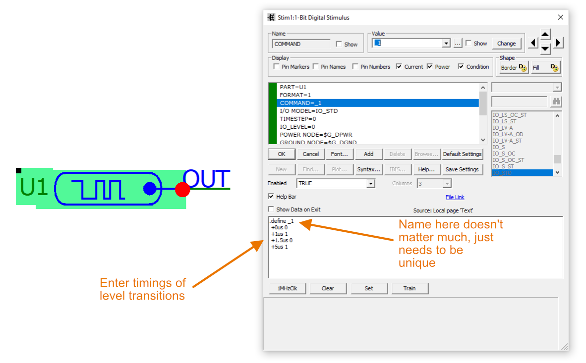
The above settings gives the following waveform if we perform a transient analysis:

Transient analysis for the 1-bit digital stimulus.

Transient analysis for the 1-bit digital stimulus.

There are four preset timings you can choose from to help you get started. These are 1MHzClk, Clear, Set and Train. The “1MHzClk” preset inserts the following text:

1
2
3
4
5
6
.define _1MHzClk 
 +0ns 0 
 +label=start 
 +500n 1 
 +1u 0 
 +1.5u goto start -1 times

Initial Conditions

Initial conditions let you specify starting values for various simulation parameters.

.IC

EXAMPLE

One such example when initial conditions are needed is to construct and simulate a NAND-based JK flip-flop. The schematic looks like this:

The simulation schematic for the JK flip-flop.

The simulation schematic for the JK flip-flop.

Without specifying initial conditions, Q and nQ will always stay in an indeterminate state. This is because one of R or S of the SR latch needs to go to 0 for the latch to be set into a valid state. But you can’t get R or S into the 0 state without one of the outputs being 1, as they are fed back as feedback into the front-end NAND gates. The simulator does not care about indeterminate states if one of the NAND gates inputs is 0, because it can become a “don’t care” signal and the simulator can set the output to 1. But for the output of a NAND gate to be 0, ALL of the inputs have to be 1.

Simulation results without specifying initial conditions. The outputs get stuck in an indeterminate state forever.

Simulation results without specifying initial conditions. The outputs get stuck in an indeterminate state forever.

We add the following initial conditions in the Text tab of the Micro-Cap “circuit” simulation:

1
.IC D(NQ)=1 D(Q)=0

A screenshot of the initial conditions added to the Micro-Cap simulation is shown below:

The initial conditions specified for the JK flip-flop simulation.

The initial conditions specified for the JK flip-flop simulation.

Now the outputs start in a determinate state, and the simulation works as expected:

Simulation with initial conditions.

Simulation with initial conditions.

More Examples

For more examples of digital simulation in Micro-Cap, see the Latches and Flip-flops page.


Authors

Geoffrey Hunter

Dude making stuff.

Creative Commons License
This work is licensed under a Creative Commons Attribution 4.0 International License .

Related Content:

Tags

comments powered by Disqus