Switched-Capacitor Filters

Switched-capacitor filters are IC components which provide analogue filtering by switching (connecting and disconnecting) capacitors.
They are an alternative to passive RC circuits, with the following advantages:
- You can build higher-order filters with less components.
- You can easily change the cut-off frequency by varying the clock frequency.
They have the following disadvantages compared to passive RC filters:
- They are generally noisier, introducing noise at the switching frequency and it’s harmonics (clock feedthru)1.
- They sample the input, and thus are subject to aliasing. Care must be taken that there are no frequencies in the input higher than half the clock frequency2.
The cut-off frequency of a switched-capacitor circuit depends on the ratio of the capacitances, and not their absolute values. Generally, the ratio of two capacitors can be more tightly controlled than their absolute values (especially in IC design). Furthermore, IC technology allows capacitor ratios to be much made much easier than resistor ratios1.
One of the biggest uses for a switched-capacitor filters is as an anti-aliasing filter before an ADC1. The filter would be configured as a low-pass filter to limit the input signal frequencies to at least half the sampling rate of the ADC to prevent aliasing.
Topologies
Most universal switched-capacitor filter ICs are arranged in the state-variable-biquad configuration, which allows for the creation of low-pass, band-pass, high-pass, all-pass and notch filters. It also allows for the design of high-Q filters with relatively low dependence on component tolerances1.
Clock Feedthrough
Clock feedthrough (or clock feedthru) is the RMS value of the clock frequency and it’s harmonics which are injected into the output of a switched-capacitor filter3. Clock feedthrough is typically tested with the input of the filter grounded.
Simulation
Unfortunately, due to limitations in the way SPICE engines are designed, the frequency response of switched-capacitor circuits cannot be directly simulated using the classic “AC analysis” method4. You can however run transient analysis at specific switching frequencies to find the gain — you can then repeat this at different switching frequencies using scripting abilities if available.
The paper AC analysis of switched capacitor filters in SPICE-family programs by Dalibor Biolek et al describes methods of creating equivalent models in SPICE programs that do allow you to perform direct AC analysis4.
Popular ICs
MF10
The MF10 is a dual 2nd order, state variable, switched-capacitor filter5. It has been produced by companies such as National Semiconductor, Maxim and Texas Instruments under variations of the MF10 part number.
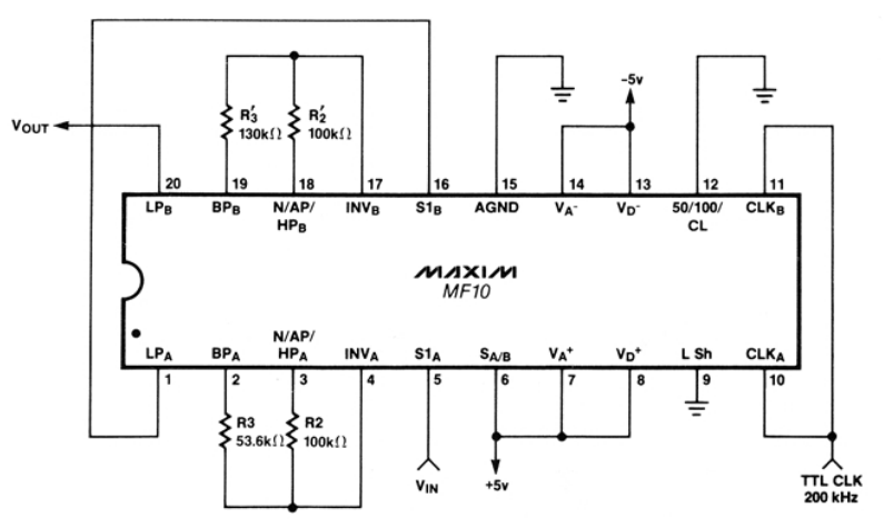
Texas Instruments has in active production the MF-10N, which is an equivalent IC in a SOIC-20 package. However, they recommend the LMF100 which is pin-compatible and has improved performance6.
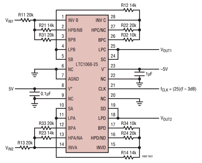
LTC1068
With 4x 2nd-order filters, the LTC1068 allows you to make up to 1x 8th order filter3.
Footnotes
-
Richard Markell (1990, Mar). Application Note 40: Take the Mystery Out of the Switched-Capacitor Filter: The System Designer’s Filter Compendium. Linear Technology. Retrieved 2022-08-29, from https://www.analog.com/media/en/technical-documentation/application-notes/an40f.pdf. ↩ ↩2 ↩3 ↩4
-
James M. Fiore (2022, May 23). 11.10: Switched-Capacitor Filters. Retrieved 2022-08-29, from https://eng.libretexts.org/Bookshelves/Electrical_Engineering/Electronics/Operational_Amplifiers_and_Linear_Integrated_Circuits_-_Theory_and_Application_(Fiore)/11%3A_Active_Filters/11.10%3A_Switched-Capacitor_Filters. ↩
-
Analog Devices (formally Linear Technology). LTC1068 Series: Clock-Tunable, Quad Second Order, Filter Building Blocks (datasheet). Retrieved 2022-08-29, from https://www.analog.com/media/en/technical-documentation/data-sheets/1068fc.pdf. ↩ ↩2 ↩3
-
Dalibor Biolek, Viera Biolkova, and Zdenek Kolka. AC analysis of switched capacitor filters in SPICE-family programs.. Retrieved 2022-08-29, from http://kit2015.aos.sk/proceedings/pdf/kolka.pdf. ↩ ↩2
-
Maxim Integrated (1996, Jul). MF10: Dual Universal Switched Capacitor Filter. Retrieved 2022-08-29, from https://datasheets.maximintegrated.com/en/ds/MF10.pdf. ↩ ↩2
-
Texas Instruments (2013, Apr). SNOS547C: MF10-N Universal Monolithic Dual Switched Capacitor Filter. Retrieved 2022-08-29, from https://www.ti.com/lit/ds/symlink/mf10-n.pdf. ↩