Load Switches

MOSFET Based
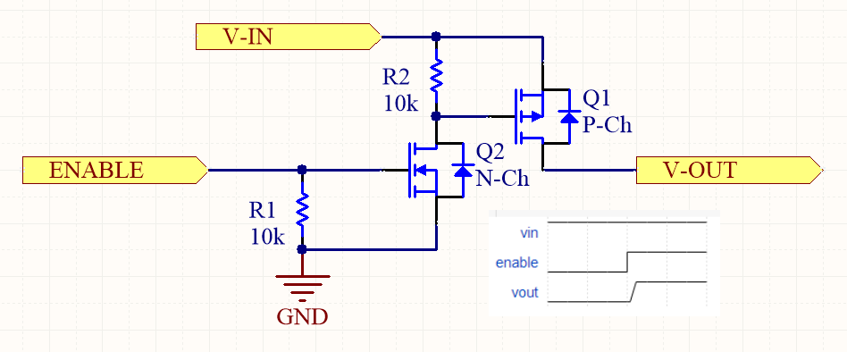
The following image shows a MOSFET based high-side switch:
BJT Current Sink Driving P-Channel MOSFET Load Switch
A simple resistor divider can be used to provide the correct to turn on a P-channel MOSFET based load switch, however that only works well if the is known and stays at fixed voltage. If it doesn’t, then the resistor divider provides a varying , which could either turn the MOSFET off at lower input voltages, or exceed at higher input voltages ( for most MOSFETs).
A better option in this case is to use a BJT current sink to set the desired across a resistor, as shown in the following diagram:
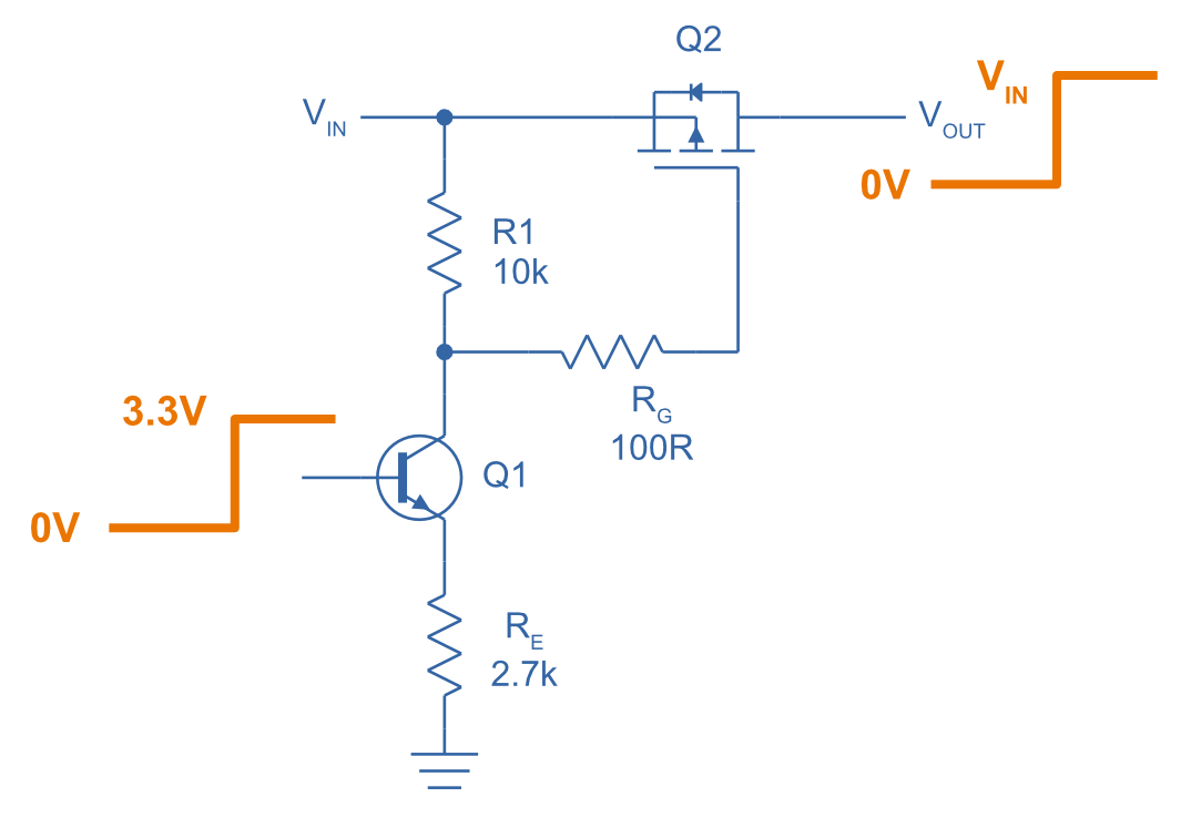
We assume the BJT () is switched with coming from a microcontroller or similar. The BJT is configured to be a simple current sink, with the current given by:
This current goes through , which provides the necessary to turn the P-channel MOSFET () on:
is added as good standard practice to limit gate current and gate voltages. In the above example, can vary from approx. (enough headroom to keep the current sink’s BJT in its active region) right up to the maximum allowed drain-source or collector-emitter voltages (for example, ), whilst keeping .
IC Based
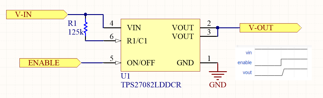
The following image shows an IC based high-side switch.
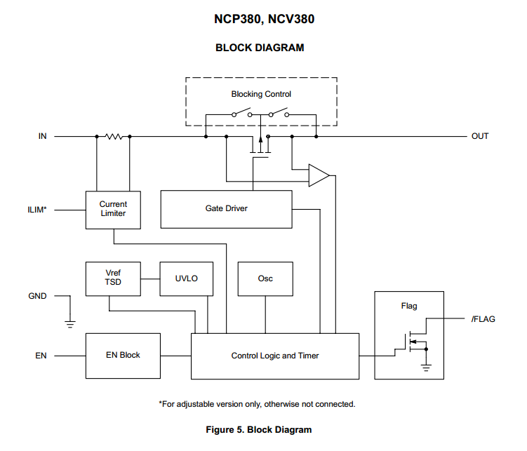
Some load-switches have reverse-polarity protection. More information of how they exactly implement reverse-protection with only the one MOSFET can be found in the The Substrate (Body) Connection section of the MOSFET page.
Be careful, some ICs which look like high-side load switches with built-in current protection are not actually suitable for switching a load. One example is the Maxim MAX15162 8V to 60V Smart Dual 1.5A Circuit Breaker with Accurate Current Monitoring IC (datasheet here).
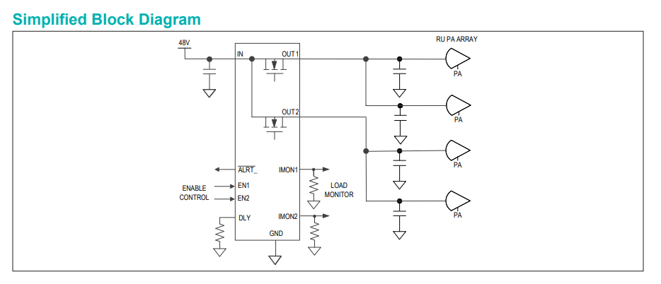
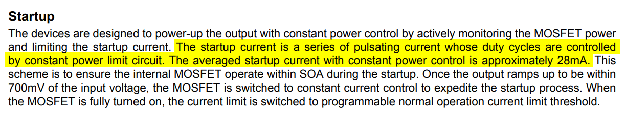
As highlighted in the below screenshot of its datasheet, during start-up it only supplies an average of 28mA to the load, even though the part is designed to pass up to 1.5A during normal operation1. If doesn’t climb to equal within 250ms during start-up, it times out. So any significant resistive load on the output that drew more than 28mA but less than 1.5A would always cause this IC time out during start-up. This suggests that it is designed to work in tandem with an external high-side switch that is placed between this circuit breaker IC and the load. If the high-side switch is kept off whilst the circuit breaker IC starts up, it will only have capacitance to charge up on its output, hence the 28mA will be ok (up to a max. capacitance, and they explain how to calculate this in the datasheet).
References
Footnotes
-
Maxim Integrated (2021, Mar). MAX15162: 8V to 60V Smart Dual 1.5A Circuit Breaker with Accurate Current Monitoring [datasheet]. Retrieved 2022-10-11, from https://datasheets.maximintegrated.com/en/ds/MAX15162.pdf. ↩ ↩2 ↩3