Components

PSoC is unique in the microcontroller industry in that you can set-up and customize basically all the hardware using a drag-n-drop GUI and schematic interface.
The IDE allows you to implement your own code in the automatically generated API files to optimise for speed (useful for fast interrupts), as long as you place it between set comment markers (otherwise it will be overwritten on the next clean-build cycle). All non-critical operations can be done using the API (which is the clean and tidy way of doing things, only insert custom code into the API files if you have to!).
This is just a personal preference, but I append the suffix Cp and then a descriptor when naming PSoC components, so that you can instantly recognise a function call to the generated API. For example,
// Two UART componentsUartCpDebug_Start();UartCpComms_Start();
// A clock componentClkCpTimer_Start();
A Note On Sleeping
Most PSoC components do not like to be slept or woken twice in a row (by calling the component API function Component_Sleep() or Component_Wakeup() twice in a row). Make sure you always call each of these API functions in sequence! Calling _Sleep() when the component is already asleep or _Wakeup() when the component is awake can cause the program to crash.
ADC (Delta-Sigma)
Delta-Sigma ADC components are high precision voltage measuring devices. The trade-off is they take longer to perform a conversion than the SAR ADCs.
ADC (SAR)
A successive-approximation register analogue-to-digital converter (SAR ADC) is the common way of measuring a PCB voltage with a microcontroller.
The PSoC ADC component supports many different sources for the voltage reference, . One of the most common choices is the internally generated 1.024V, which allows you to measure a voltage between 0-2.048V. For ratiometric measurements (e.g. measuring the voltage of a thermistor temperature sensor connected in a resistor divider configuration), you can set to be VDDA/2. Please note that you cannot change the voltage reference for the ADC at run-time (i.e. it may only be adjusted at compile time).
Some of the higher-end PSoC microcontrollers contain 2 SAR ADCs. Remember that with an analogue multiplexor, you can use one ADC to take successive measurements of large numbers of analogue channels. And if you need precisely consecutive measurements, you still only need one ADC if you add ‘sample and hold’ components to the analogue inputs.
The higher-end PSoC microcontrollers also have Delta-Sigma ADCs, which are more accurate than the SAR ADCs (albeit with a slower conversion time).
Analogue Multiplexer
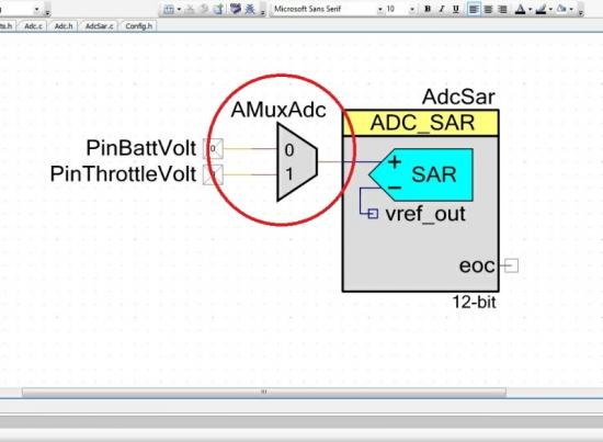
The PSoC has some powerful analogue multiplexing capabilities. This includes multiple analogue multiplexors that can accept up to 31 inputs. The multiplexer also has the ability to connect more than one signal at a time, providing “cross-bar support”. This means you can essentially connect any analogue signal to any other (it makes the meaning of an ‘input’ to the mux rather ambiguous, as it now could be an output).
The following picture shows a PSoC multiplexer being used to connect two analogue inputs up to an ADC (one of the most common uses for an analogue multiplexer).
Cap Sense
The cap sense component allows you to use capacitive touch sensing PCB components with a PSoC. The only external component required by the cap sense is a capacitor, which is used for transferring charge to and from the cap sense pins. The capacitor pin is automatically added to the pin listing when you add a cap sense component, don’t forget about this pin! Unusually, it can be routed to almost any pin on the microcontroller (most other pins used for capacitors (such as the ADC bypass cap) are limited to one or two pin choices).
The cap sense component supports buttons, linear sliders, rotational slider, and more. Buttons are recommended to be about 10mm in diameter.
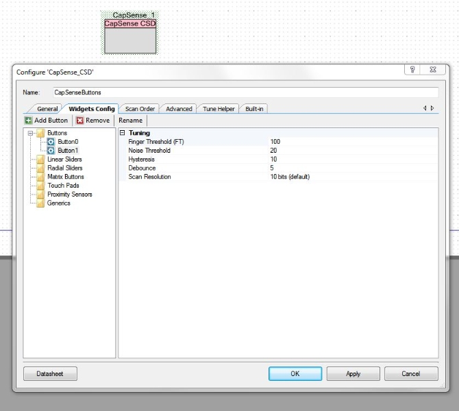
PSoC 3 and 5 devices feature a powerful inbuilt cap sense peripheral which is tightly integrated with a cap sense module in PSoC Creator which can be used to set up and configure the cap sense. The module supports buttons, sliders (both linear and radial), matrix buttons, touch pads and proximity sensors. They can all be set up graphically with not a single line of code needed to be written. Always remember to add a modulation capacitor (typically 2.2nF) to one of the PSoC pins when using cap sense.
The cap sense peripheral uses a delta-sigma modulator.
The screenshot below shows the GUI for configuring the capacitive elements in PSoC Creator.
Clocks
Frequency Range: 0Hz - max supported frequency of IC
In the PSoC IDE, clock sources are counted as components also! You can drag-n-drop a clock component onto a schematic to provide a clock source to any other component that requires it. You can set the frequency that you want, and the IDE will automatically configure the component with the right divider values to provide the frequency you want, and will warn you if it can’t generate one to match the frequency and tolerance you specify. This is great as it removes all the #define COUNTS XTAL_FREQ/DESIRED_FREQ constants you usually have to create to make portable, crystal independent code to run peripherals.
The clocks can work with the internal PLL (phase-locked loop), to generate higher frequency clocks than the oscillator/crystal frequency.
Take care if using a clock to reset a PSoC hardware component. PSoC clocks have a 50% duty cycle, and reset inputs are usually level-triggered rather than edge-triggered. For that reason, if you connect a clock directly to a reset input pin, the clock will hold the component in reset for half its period. This is probably not what you intended. To fix it so that the clock resets the hardware component on the rising-edge only, add an edge detect component between the clock and the reset input.
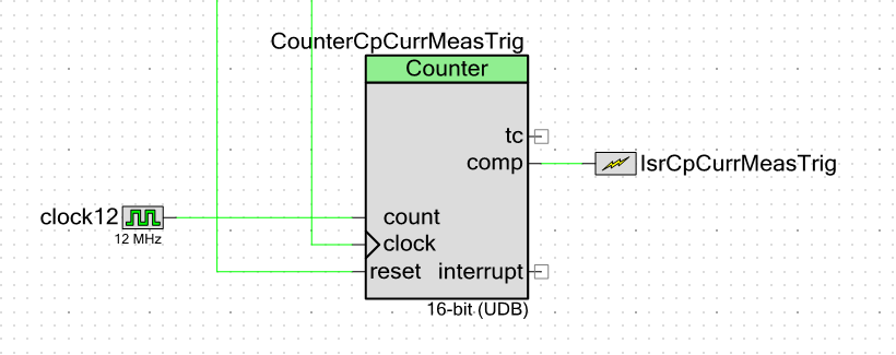
Counter
| Available Resolutions: | 8, 16, 24, or 32-bit |
| Clock Mode: | Down counter (default), up counter, clock with up and down count, clock input and direction |
| Interrupt Triggers: | TC (period), compare, capture |
| Run Modes | Continuous, one-shot |
| Other Features | Optional compare output and capture input. Enable and reset inputs (these functions can be controlled from both firmware and hardware) |
Most embedded engineers would have heard about counters. They are commonly included peripherals in microcontrollers. Counters enable you to, well, count stuff. PSoC has a highly configurable and flexible counter module. Its counting modes support counting down (the typical method), counting up, or counting in both directions depending on an input bit. It has a user defined clock input, compare register and output, a capture mode, and an interrupt with configurable interrupt sources. The maximum count can be set to 8-bit, 16-bit, 24-bit or 32-bit.
One gripe with the up-down counter is that when counting upwards, you cannot get it to reset to 0 at a configurable count. It only supports reset on overflow (which can be , , or ). I encountered this problem when designing a hardware based quadrature encoder counter for BLDC motor control (although Cypress does provide a separate Quadrature Decoder component).
PSoC 3 and 5 support both UDB and FF (fixed-function) block counters, while PSoC 4 only supports the FF block counters.
Debouncer
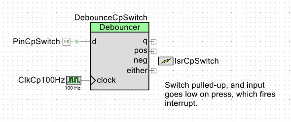
Cypress provides a handy hardware component that deals with the issue of switch debouncing, without having to use any software.
The component is really easy to set up and use, and the following image shows one of the most common ways you would set up the debouncer circuit.
Delays
Cypress supplies functions for creating software halt delays. They are included in CyLib.c. There is:
void CyDelay(uint32 milliseconds);void CyDelayUs(uint16 microseconds);On the Cypress forums there are also delay functions supplied in a C header (.h) and assembly (.asm) file.
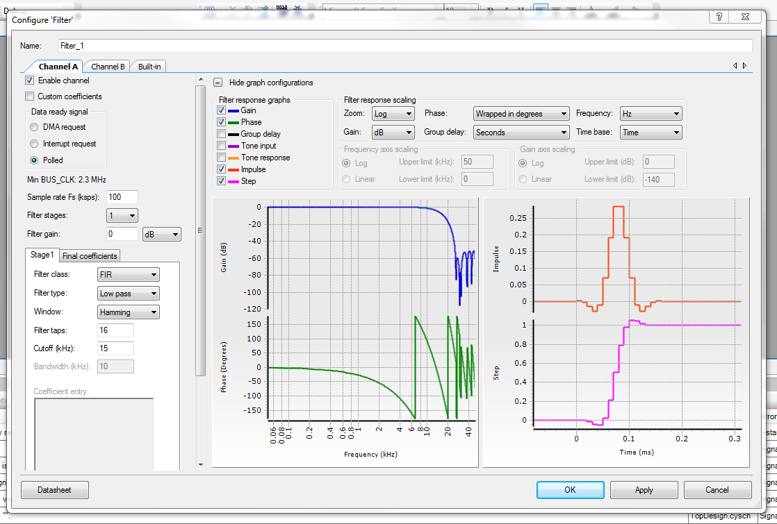
Digital Filter Blocks (DFBs)
The PSoC microcontroller features a digital filter block, a highly versatile and easy-to-use piece of digital hardware that can be configured graphically from the GUI.
I2C
Info Last Updated For: I2C v3.5
The I2C component can be used to make the PSoC act as an I2C master or slave device, and allows communication with other I2C devices. It also supports multi-master buses.
Low-Level vs. High-Level Master API Functions
The PSoC I2C component provides both low-level and high-level API functions.
Low Level Master Functions:
I2C_MasterSendStart(uint8_t slaveAddress, uint8_t R_nW)I2C_MasterSendRestart(uint8_t slaveAddress, uint8_t R_nW)I2C_MasterSendStop()I2C_MasterWriteByte(uint8_t theByte)I2C_MasterReadByte(uint8_t acknNak)High Level Master Functions:
I2C_MasterWriteBuf()I2C_MasterReadBuf()When reading bytes individually from the I2C bus using the low-level API, remember to make sure the last byte is not acknowledged (i.e. NAK instead of ACK).
The low-level I2C API functions can cause your application (or thread) to lock-up due to dangerous while() loops (see below). The higher-level functions have the advantage of always returning.
Dangerous While() Loops
In what I see as a rather poor design decision, some of the low-level PSoC I2C API functions have while() loops which, under certain conditions, never terminate. In a single threaded application (e.g. a mega-loop structure), this would cause your entire app to lock-up (except for interrupts). In a multi-threaded application, this would cause the calling thread to freeze. In any case, this is bad!
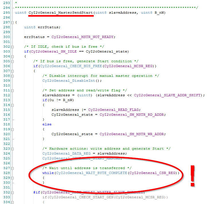
The following API functions in I2C_MASTER.c contain unbounded while() loops:
`$INSTANCE_NAME`_MasterSendStart()`$INSTANCE_NAME`_MasterSendRestart()`$INSTANCE_NAME`_MasterSendStop()`$INSTANCE_NAME`_MasterWriteByte()`$INSTANCE_NAME`_MasterReadByte()The following macros in I2C.h contain unbounded while() loops:
`$INSTANCE_NAME`_GENERATE_START_MANUAL`$INSTANCE_NAME`_GENERATE_RESTART_MANUAL`$INSTANCE_NAME`_GENERATE_STOP_MANUAL`$INSTANCE_NAME`_TRANSMIT_DATA_MANUAL`$INSTANCE_NAME`_READY_TO_READ_MANUAL`$INSTANCE_NAME`_ACK_AND_RECEIVE_MANUALThe only workaround I know of is to modify the PSoC I2C component (not nice, I know!) and add an upper-bound to the number of iterations of the while() loops.
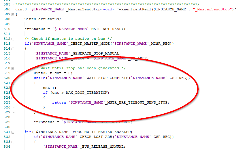
Note that 5 new timeout error responses (e.g. `$INSTANCE_NAME`_MSTR_ERR_TIMEOUT_SEND_STOP) have been added as macros so the user code can determine if a timeout has occurred.
Interrupts
Most of the work in setting up an interrupt can be done graphically. When starting an interrupt, you can provide a function pointer to call instead of using the pre-defined version (which helps keep your code separated from the automatically generated Cypress stuff).
To declare a interrupt function (i.e. the prototype, the bit at the top of your file), use the following macro, where the ISR function name is the name of the function you want called when the interrupt occurs. For example:
// A function prototype for an interrupt// This goes near the top of the .c fileCY_ISR_PROTO(UartRxISR);To define the function (the actual interrupt code), do not just use the standard function syntax. Instead, use:
// An ISR function definition.// This one is for a UART receive interrupt// Notice the CY_ISR() macro, this is provided by// Cypress to increase portability.CY_ISR(UartRxISR) { // Do something in interrupt}To get this function to be called from an interrupt, you need to pass the function address into the Cypress code for that interrupt when the interrupt is started. This is done by using the Isr_StartEx() command as opposed to the standard “Start”. For example, if there was an interrupt called ISR_UART_RX attached to the receive interrupt source (this is done graphically), the code would be:
ISR_UART_RX_StartEx(UartRxISR);which would call the interrupt handler function UartRxISR() defined above.
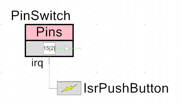
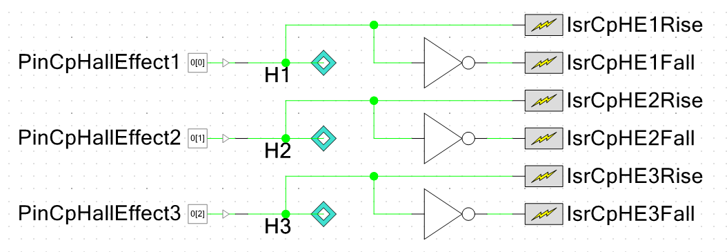
Note that the trigger mode for interrupts can only be set to rising edge or level, falling edge is not supported. However, you can use the power of the reconfigurable PSoC hardware to get around this. If you want to detect a falling edge, set the trigger mode to rising edge and put an inverting gate on the input to the interrupt. If you want to trigger on both edges, you can use two interrupts, with one before the inverting gate, and one after.
If you are using a PSoC 5/PSoC 5 LP, you can use the ARM Cortex-M3 NVIC_IABR0-NVIC_IABR7 registers to determine whether an ISR is currently being executed. These registers span the address range 0xE000E300-0xE000E31C. See this link for more information.
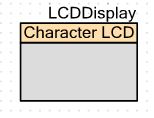
LCD Drivers
One of the disadvantages of the character LCD driver is that it requires 7 consecutive pins on a port, beginning at either pin 0 or pin 1. This kind of goes against PSoC’s ‘route anywhere’ maxim.
Pin description:
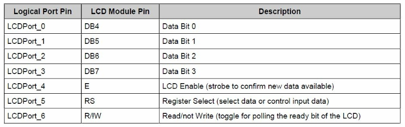
Pins
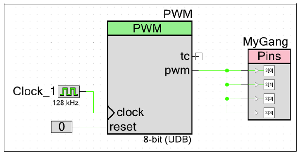
Yes, even the microcontroller’s physical pins are “componentised” in PSoC Creator. This makes interfacing to the outside world easy! Pins can be connected directly to hardware on the schematic (so no code is needed to control it), or set so that an API is generated (so you can control it via code). Once the pin is created, you assign it a physical location in the system design window.
Pins on a PSoC microcontroller can be “ganged” together to provide more output current. They can be connected together in hardware (via the PSoC Creator schematic, as shown below), so you don’t have to worry about setting them all at the same time in software. You must still make sure that the total amount of current for a port is not exceeded.
USB Pins
Most physical pins on a PSoC microcontroller can be connected to a GPIO pin component. One caveat is that you have to set the pin component to either “strong drive” or “open-drain pull low” before you can assign it to one of the two USB pins (D+, D-, or P15[6] and P15[7] on the PSoC 5/PSoC 5 LP). This is also mentioned on the PSoC Bugs, Problems And Annoyances page.
Synchronisation
By default, digital inputs are double synchronised, and analogue inputs are left alone (it makes no sense to synchronise an analogue signal). This is normally a good thing, since it will make your external signal compatible with internal PSoC digital logic. Note that synchronisation will modify your input signal. With a fast enough system clock, this is normally a non-issue since the edge-shifting will be small compared to the period of your signal.
However, you can turn the synchronisation off in the pin settings if you wish to have an asynchronous signal.
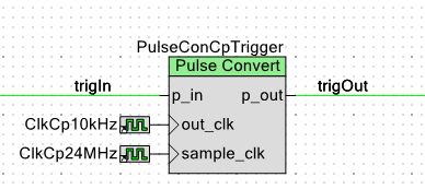
Pulse Converter
The Pulse Converter component is useful to convert variable width input pulses into constant width output pulses. It is a purely hardware-based component, using two different clock inputs to change the pulse width.
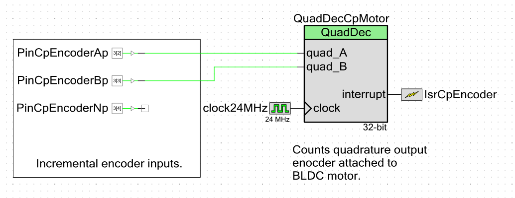
Quadrature Decoder
The quadrature decoder is a useful component when interfacing with incremental encoders. It accepts A, B and N (optional) channel quadrature inputs, and converts the pulses into a count. The count is configurable to be 8, 16 or 32-bit. You can select to count on every pulse transition for the highest resolution (4 per ‘pulse’), to just one per pulse. It also features glitch filters and a configurable interrupt source. The interrupt source does not have a compare feature, so one of the let-downs is that most of the processing of the count has to be done by software polling.
I have used this for controlling a BLDC motor that had an incremental encoder attached to its shaft and it worked perfectly! The picture below shows the component connected to the input pins of the incremental encoder. The N channel was not used as I did not want the count to be reset every cycle.
RTC
RTC clock functions are provided that perform some rather neat and advanced functions. The core capability of the RTC is to keep track of the time. However it also extends the time keeping function by keeping track of hours/days/weeks/year, allows alarms to be set (based on flexible criteria such as the 10th minute of every hour or a one-off set time), and can even accommodate for daylight saving!
The RTC code is supplied as a component that you drop into the top level design in PSoC Creator.
Serial Communication Block (SCB)
While the PSoC 3 and 5/5LP microcontrollers have dedicated UART, I2C and SPI modules, in the PSoC 4 they are all bundled together in a Serial Communication Block (SCB).
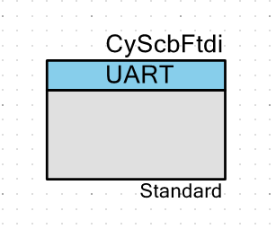
TopDesign.cysch file in PSoC Creator. This SCB block is configured as a UART.The SCB can be either configured graphically at compile time or by using code at runtime to operate as a UART, I2C or SPI module.
Timer
The Timer component is very similar to the Counter component.
UART
As an embedded developer, this is one of the PSoC components you will use most frequently! The PSoC UART is easy to setup and powerful. It supports many baud rates, parity, stop bits, a voting system for noise reduction, a multitude of interrupt sources, and both hardware and software receive/transmit buffers. It does not support auto-baud.
Careful consideration of the UART must take place when using the sleep modes of the microcontroller, or your messages will become truncated/corrupted.
The sample code below assumes you have set up everything via the schematic UART component.
// Initialise the UARTUart_Start();
// Send a messageUart_PutString("My first string!");
USB2UART
Cypress has released a USB2UART driver for the PSoC 3 and PSoC 5 range. It allows you to emulate a COM port over a USB connection. Really useful for passing information easily from a microcontroller to a computer! This emulation gets rid of bulky COM ports and RS232 to UART drivers, since all the hardware is contained within the PSoC device. Data is sent/received on the microcontroller through a nicely built API, and sent/received on the computer like any standard COM port communication (e.g. a terminal program or .NET/COM API).
USB
Supports full-speed USB. However, there is no USB host support, so the PSoC always has to act as the device. Some PSoC 3 devices with 32kB or more of flash support USB, as well as PSoC 5 devices.
The USB module supports interrupt, control, bulk and isochronous transfer types. It provides support for bootloading, HID (human-interface device), audio classes, MIDI devices, and CDC classes.
VDAC
The VDAC (digital-to-analogue voltage converter) component is used to convert a digital value into an analogue voltage. It is the opposite of an ADC.
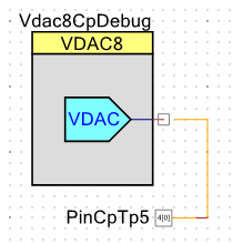
The VDAC component can be very helpful while debugging. You can use it to “trace” where the execution point of the processor is. While a digital output port only allows 0 or 1, because the VDAC output supports 256 output levels, you can assign a level to a specific function or block of code, and use an oscilloscope to inspect where the processor is. Each different voltage level shown on the oscilloscope will correspond to a different section of code.
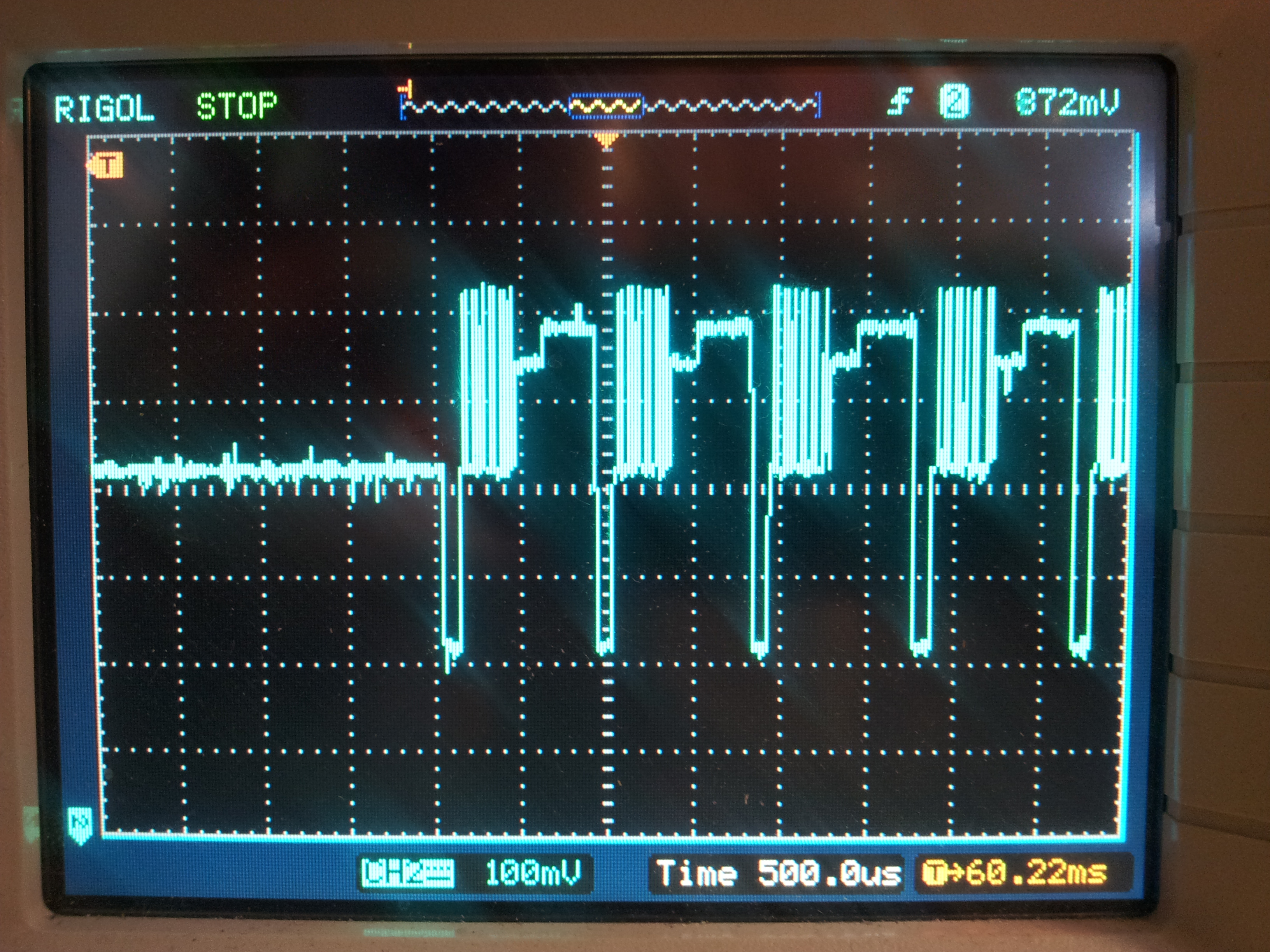
This technique gives you both the execution time of a block of code, as well as the order of execution, which is important to know when running an embedded operating system (such as FreeRTOS).
void main() {    VDac8_SetVoltage(0);    VDac8_Start();
    while(1) {        WatchedFunction();    }}
// This is a watched function. You// will be able to determine the code execution times// of its different parts based on the voltage output// by the VDAC component.void WatchedFunction() {    VDac8_SetVoltage(100);    // Code here...    VDac8_SetVoltage(200);    // More code here...
    // Reset VDAC to 0V    VDac8_SetVoltage(0);}
Watchdog
Info last updated for: cy_boot v5.20.
Some PSoC microcontrollers have a built-in hardware watchdog. Because the watchdog is built into the silicon, it is not included in the PSoC Creator Component Catalog, and is not shown on the schematic design (.cydwr file).
The ILO (internal low-speed oscillator) is used to provide the watchdog with a clock source.
The watchdog is started with the function CyWdtStart(). Note that once you make a call to CyWdtStart(), there is no way to disable the watchdog until an IPOR (imprecise power-on reset) event occurs. This is a purposeful design choice for application safety.
NOTE: Although it seems like once you call CyWdtStart(), you are guaranteed that the device will reset if the watchdog is not fed, there is one exception. Putting the PSoC microcontroller into the hibernate sleep mode will also halt the watchdog timer!
The watchdog is cleared (a.k.a. fed) with the function CyWdtClear(). This must be called periodically to prevent the watchdog from resetting the microcontroller.
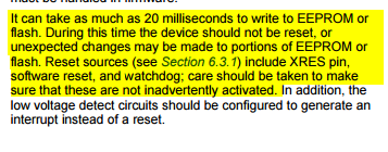
Care must be taken when a watchdog is activated for an application that writes to either flash or EEPROM. It can take up to 20ms to perform a flash/EEPROM write, by which time the watchdog could trigger and cause a reset.