Heatsinks And Thermal Interfaces

Heatsinks
Heatsinks are used in circuit design to conduct heat away from a component faster than what air would do, usually to prevent high-power components from overheating and failing.
Typical components that require heatsinking are high current linear regulators, MOSFETs on H-bridges, power amplifier BJTs and MOSFETs, and power limiting resistors. Most heatsinks are made from black anodized aluminium.
Their heatsinking capability is rated with a thermal resistance, which has the units . Common packages that heatsinks are made for include TO-220 and SOT-223.
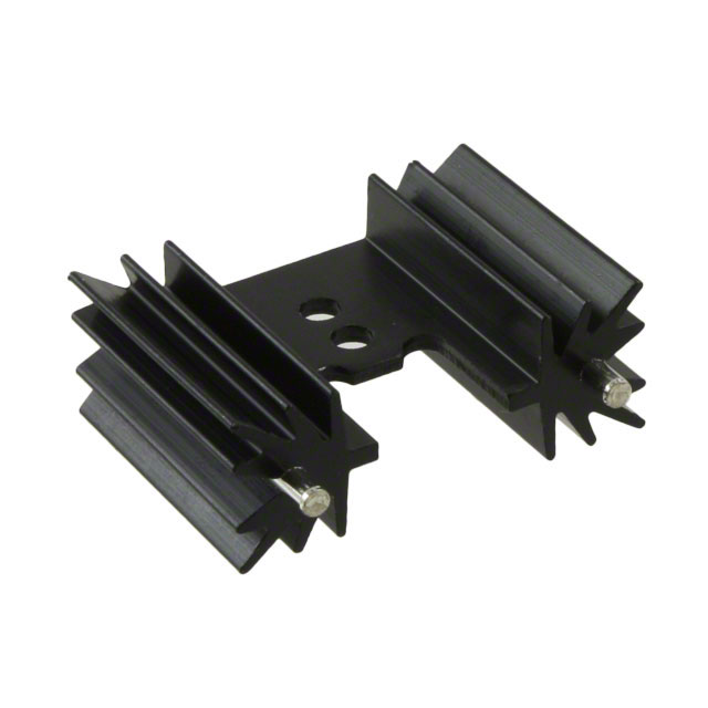
You can get heatsinks with twisted fins, which gives better cooling due to increased air turbulence and convection flow.
Phase change compounds can be used as thermal pads. Phase change compounds are designed to be solid at room temperature but become liquid at the operating temperature, which gives a better bond between the component and heatsink, lowering its thermal resistance.
For more information on thermal resistances, see the Thermal Management page.
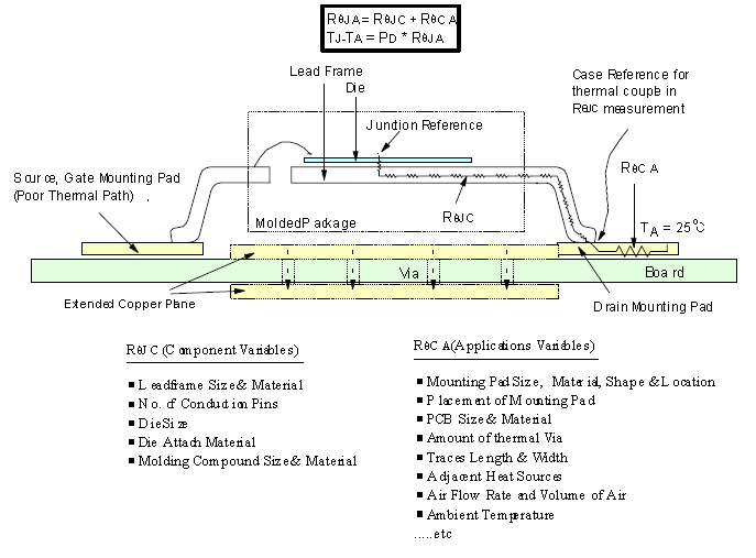
Where Does The Heat Go?
The following diagram is a thermal analysis of a SMD MOSFET mounted to a PCB.
List Of Component Package Thermal Resistances
See the Component Packages page. This has many of the common component packages and their thermal resistances.
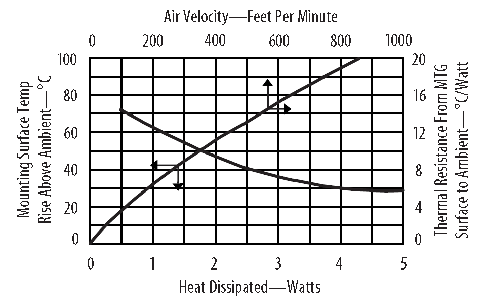
Forced Convection
The following image shows two graphs combined into one, the thermal performance of a heatsink with natural convection, and that with forced convection (e.g. a fan).
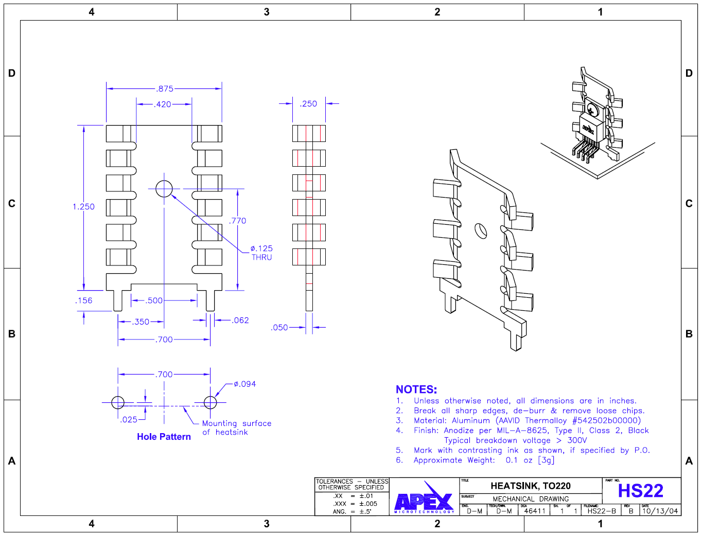
Packages
There is no standard package for heatsinks and the pitch for their support pins, although some more common pin spacings exist (such as 25.4mm (1 inch) etc.).
Thermal Interfaces
Two packaging types:
- Pad
- Roll
The thermal interface material may be filled with ceramic particles to improve thermal conductivity.
Polymer with acrylic adhesive.
Sometimes the electrical resistivity will not be specified, but a dielectric strength (in kV/mm) will be given. This is when the electric field becomes strong enough to pull outer valence electrons away from the material’s atoms, and the material becomes conductive.