Light-emitting Diodes (LEDs)

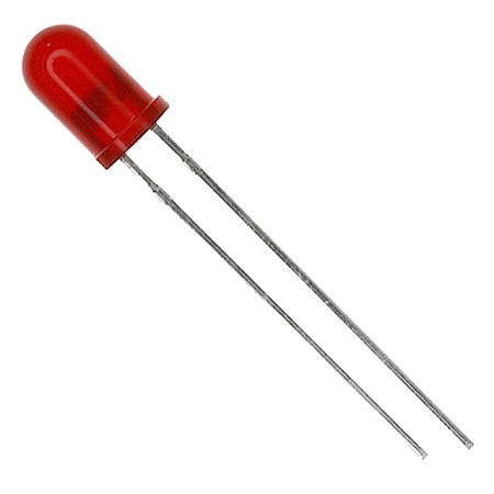
Light-emitting diodes (LEDs) are basic active (non-linear) electronic components which when provided with voltage and current, emit light. Although there are many ways to make light from electricity (hot filaments, lasers, plasma, etc.), by-definition LEDs are built from a basic diode. They typically have two electrical connections, just like a standard diode. They emit light when forward biased, and block reverse current just like normal diodes (a warning here: some LEDs DO NOT like being reverse biased, please read the datasheet).
Schematic Symbol
The schematic symbol for a LED looks like a diode symbol, but with arrows added to indicate that it gives off light. The schematic symbol for a LED is shown in This is a placeholder for the reference: fig-led-diode-schematic-symbol. As with a normal diode, the anode is on the left, and the cathode on the right.
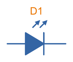
A more positive voltage is needed on the anode w.r.t to the cathode for current to flow through the LED and it emit light.
Important Parameters
Parameters are sorted alphabetically.
Dominant Wavelength
- Symbol:
- Units (typical):
This is the wavelength of the apparent color the human eye “sees” the LED as. It is a photometric quantity, and is not the same thing as the peak wavelength. Normally measured in nanometres ().
Flux
This will be used as a shorthand for either radiometric flux, spectral flux or rarely, photon flux. You will have to deduce which based on the context.
Forward Current
- Symbol:
- Units (typical):
This is the maximum forward current the LED can continuously be driven at. For small indicator LEDs, the maximum forward current is typically 20-30mA. Normally an indicator LED with a max. forward current of 20mA would be driven at less than the max., somewhere between 2-10mA.
Forward Surge Current
- Symbol:
- Units (typical):
Normally rated at a fixed temperature, duty cycle, and pulse length.
Forward Voltage
- Symbol:
- Units (typical):
Rated at a fixed forward current.
LED forward voltages for common LED colours are listed in This is a placeholder for the reference: tbl-led-forward-voltages. You will notice that the forward voltage increases with the increasing frequency of the light (in simple terms, it takes more input energy to create photons with a higher energy), and the forward voltage is largely independent on the manufacturer or manufacturing process of the LED.
| Colour | Forward Voltage |
|---|---|
| Red | 2.0V |
| Orange | 2.0V |
| Yellow | 2.1V |
| Green | 2.2V |
| Blue | 3.3V |
| UV | 3.0V (UVA) to 7.5V (UVC) |
Irradiance
- Symbol:
- Units (typical):
Irradiance is the power received per unit area of a surface which is illuminated by a light source. Irradiance is usually denoted with the symbol as is already used for radiant intensity. It is a radiometric quantity.
Peak Wavelength
- Symbol:
- Units (typical):
The wavelength at the peak of the spectral density curve. This is the wavelength at which the LED emits the most power (or flux). It is a radiometric quantity, and is not the same thing as the dominant wavelength.
Photon Flux
- Symbol:
- Units (typical):
The number of photons emitted per second by the LED. This is a not a common property to be listed on LED datasheets, more typically the radiometric flux is given.
Photosynthetic Flux
- Symbol:
- Units (typical):
Very similar to photon flux, except only photons within the photosynthetic active region (PAR) of 400-700 nm are considered. Commonly used for LED light sources that will be used in agriculture for plant growth (e.g. high-pressure sodium lamps). Typical values range from 100-200 umol/s.
Radiation Pattern
- Symbol: n/a
- Units (typical): Relative intensity (0-1)
The radiation pattern (aka spatial distribution) is usually given on a semi-circular graph, showing the relative intensity of the emitted light vs. the angle from looking directly forward.
Radiant Flux
- Symbol:
- Units (typical): Watts,
The radiant flux (also called the radiant power) is the total amount of light energy per unit time radiated from one region to another. In the context of an LED it is typically used to describe the total amount of light energy emitted by the LED each second. You can divide the radiant flux by the input power to calculate the efficiency of the LED, and to find out how much power will be lost as thermal energy. It is different to the photometric flux.
Reverse Voltage
- Symbol:
- Units (typical): Volts,
The maximum voltage the LED can withstand when reverse biased. Typically LEDs are forward biased but in some applications their diode property of only allowing current to flow in one direction is used.
View Angle
- Symbol:
- Units (typical): Degrees,
The viewing angle (a.k.a. view angle) is the total angle that the LED light output encompasses before the light radiance drops down to 50% of its peak. This should be less than 180° as most LEDs emit light off a planar surface. The smaller this value the more focused the LED is. Some LEDs come packaged with a lens to focus the light. It is called because is the angle measured from the center to where the radiance falls to half the peak, thus the total angle is twice this. It is assumed that the view angle is the same for any cross-sectional plane of the LED, for most LEDs this is true as their radiation pattern is rotationally symmetric (around the axis pointing forwards).
Another definition of this is the angle until the light radiance drops down to 50% of what it emitted from center1. This is the same as the above definition as long as the LED emits the most amount of light directly forward, which is true for a large number of LEDs.
Limiting The LED Current
A common mistake when working out the value of a current limiting LED resistor is to forget to include the forward voltage drop of the diode into the equations. This has a bigger effect when running the LED at lower voltages. The equation for working out the resistance needed to limit the current in an LED is:
where:
is the resistance required in series of LED to limit current, in
= supply voltage driving the LED (typ. 3.3, 5, 12V), in
= forward voltage drop of the led (typ. 2.0V), in
= required current through the led (typ. 5-20mA), in
LED Current-Limiting Resistor Calculator
Use the calculator below to work out the series resistor needed to drive an LED at a desired current. Pick a colour to use a typical forward voltage from the table above, or select Custom to enter your own . The required resistance is calculated using Ohm’s law, , and the resistor power dissipation as . Inputs accept metric prefixes (e.g. 5, 20m, 3.3V).
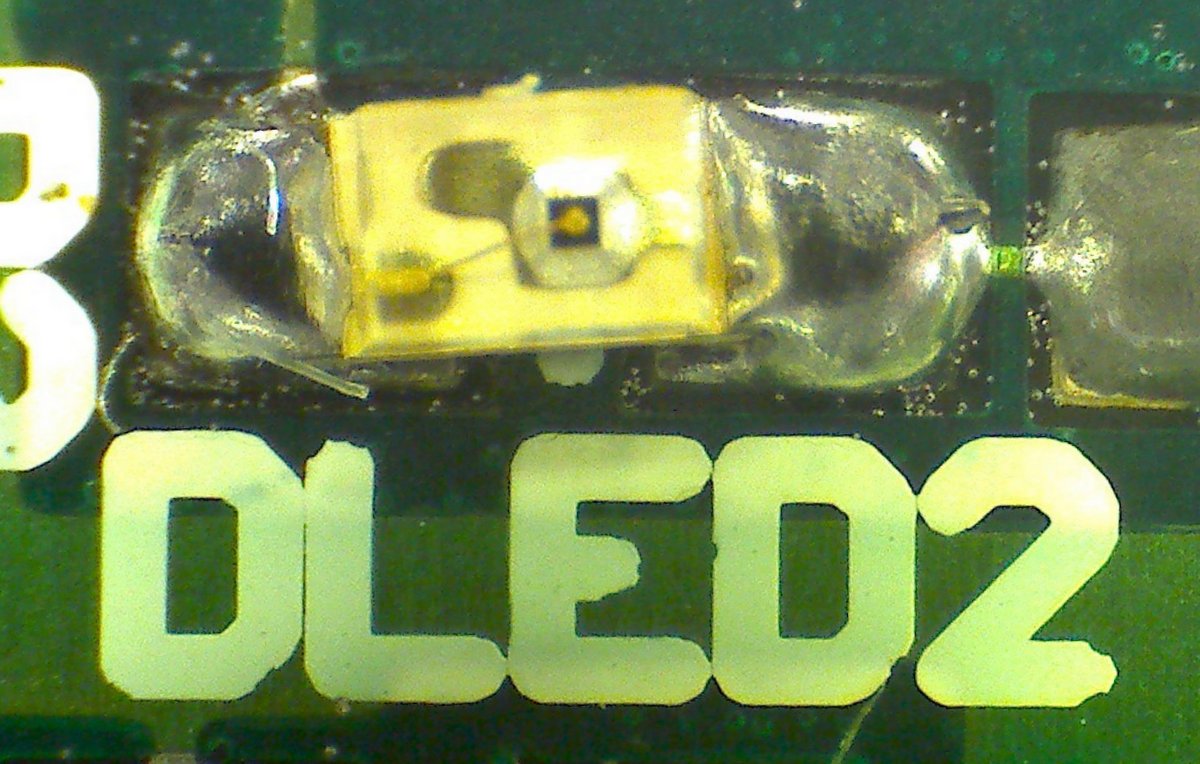
Reverse Mounting
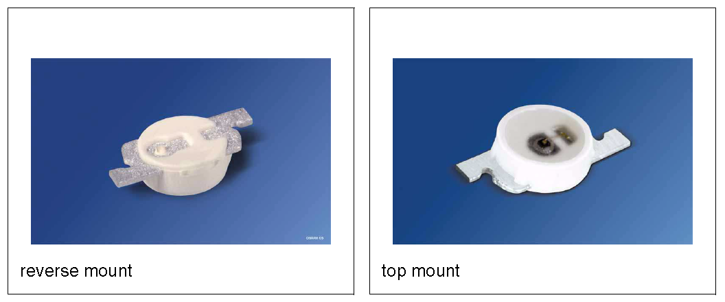
Reverse mounting LED’s are SMD LEDs which have the light source emitting in the reverse direction, e.g. toward the PCB they are mounted on. A hole is drilled in the PCB to let the light through to the other side. They are useful when using a PCB as a user interface panel, or when you want to use light guides (since the light guides can be mounted up against flat PCB).
Multiplexing
Multiplexing is a way of connecting LED’s in an arrangement so that it minimises the number of microcontroller pins required to drive them. There is also a even greater pin-saving method, known as Charlieplexing.
Multiplexing is normally done in a row/column configuration, where the LED’s are connected in a grid-like fashion, and one microcontroller output pin is used for each row and column. This gives the following equation linking the number of pins used and the number of LEDs:
where:
= number of LEDs
= number of microcontroller pins
Charlieplexing
Charlieplexing is a more efficient (in terms of number of drive signals used) way of driving LEDs, compared to multiplexing.
The following equation is given linking the number of pins used and the number of LEDs:
ESD
Even though all LEDs are susceptible to ESD damage, it is the GaN based LEDs (blue, white and some green colors) that are more sensitive to surge voltages caused by ESD.
The susceptibility for LEDs to ESD is low enough that no extra ESD protection measures (aside from the current-limiting resistor which acts somewhat as a ESD suppressor also) are taken for LEDs used for general purposes.
Light Detection With A LED
A little known fact about LEDs is that they can be used for light detection. Although not as sensitive as purpose-built photo-diodes, with a few external components, can be interfaced with a microcontroller and be used to detect variations in the light level.
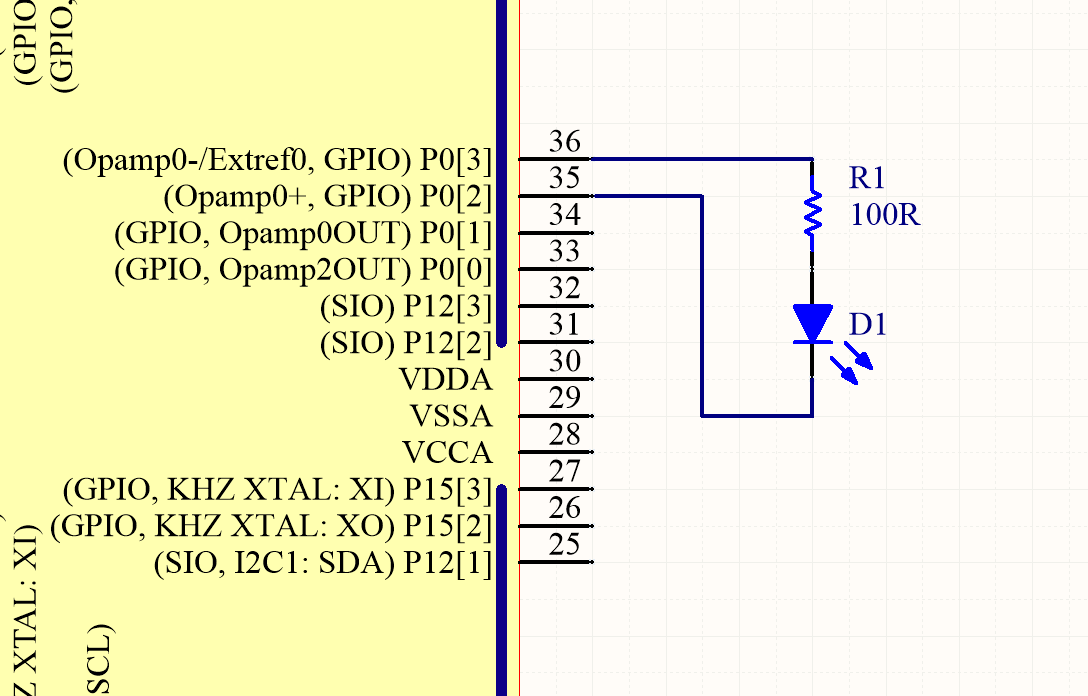
The schematic in This is a placeholder for the reference: fig-led-connected-to-micro-for-light-detection-schematic shows how to connect an LED up to a general microcontroller for light detection. The LED and resistor are connected up to GPIO pins.
The photocurrent of an LED is about 10-100 times smaller than that of a purpose-built photo-diode. The wavelength of peak sensitivity is usually a little less than the peak wavelength that it emits light at.
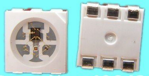
RGB LEDs
RGB LEDs are LED’s which have three diodes inside them, one red, one green, and one blue. Whats neat with these is, when controlled correctly they can produce almost any visible colour (remember primary colours in science class?).
RGBs usually have at least four pins, one each for one side of the red, green, and blue diodes (either all anode or all cathode), and a common which connects all three of the other sides of the diodes. They are more complicated to control than a normal LED, normally requiring 3 different PWM signals, and a bit of firmware to calculate the appropriate duty cycles.
You can get RGB LEDs which already have the control and drive circuitry (e.g. the constant current source) for the LEDs inside them. These are normally connected to a microcontroller via a digital communication bus (e.g. SPI), or sometimes a custom protocol).
One popular example, the Worldsemi WS2811, uses its own custom communications protocol running at 800kHz.
Overview of Worldsemi’s RGB LED product offering:
- WS2811: LED driver IC, no built-in LEDs.
- WS2812: Combined RGB LED and driver IC.
- WS2812b: Upgraded version of the WS2812. This includes added reverse polarity protection, higher brightness and colour uniformity, better pinout (a drop from six pins in the WS2812 to only four pins in the WS2812b), better heat dissipation (lower junction to case thermal resistance)2.
The WS28xx series of LEDs uses a custom, 1-wire, daisy-chainable protocol for communication. This is a placeholder for the reference: fig-ws2812b-typical-application-schematic shows an example application schematic showing how they can daisy-chained together. Microcontroller SPI peripherals running at 16x the WS28xx bit rate can be used to generate the data stream.
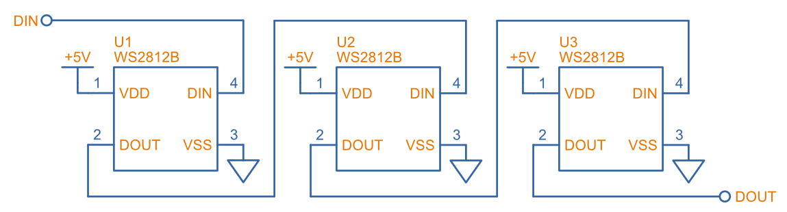
For information on how a MCU SPI peripheral can be used to send data to a WS2812 LED, see the SPI Communication Protocol page.
UV LEDs
UV LEDs are used for applications such as:
- UV curing (UVA: 365-405nm)
- 3D printing/additive manufacturing
- Disinfection and sterilization (UVC: 220-280nm)
- Photocatalytic oxidation (PCO) (which is related to sterilization)
- Fluorescence
UVC light is especially effective at killing bacteria and viruses (germicidal effect). This is a placeholder for the reference: fig-germicidal-effectiveness-of-uv-light-graph shows the germicidal effectiveness of UV light vs. its wavelength.
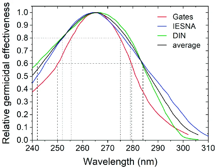
The germicidal effectiveness is normally quantified in terms of a log reduction. The log reduction is the common logarithm (i.e. base 10 logarithm) of the ratio of the number of microbes before and after the UV light is applied. For example 1 log reduction would be a 90% reduction in the number of microbes and a 2 log reduction would be a 99% reduction in the number of microbes.4
The dose of UV light required is usually specified as . The dose is rather complicated to calculate as it depends on a large number of factors including the microbe type, UV wavelength, humidity, irradiation time and other factors. However, roughly speaking, doses between 2-10mW/cm2 can give a 1 log reduction for a large number of microbes.5
UV LEDs are used in photocatalytic oxidation (PCO) systems. This is where the UV light is shined onto a photocatalytic substrate, typically titanium dioxide (TiO2). The TiO2 generates free radicals (OH hydroxyl radicals) which are able to perform oxidation reactions. Titanium oxide PCO has a energy band gap centered around 360nm, which is in the middle of the UV-A range.6 This is a placeholder for the reference: fig-photocatalytic-oxidation-diagram shows a diagram of the process.

Interestingly, PCO with TiO2 can also be used to oxidize ethylene gas (C2H4) into CO2 and water. This has the benefit of preventing fruit from ripening to quickly (ethylene gas plays an important role in this, so destroying it slows it down).8
LED Controllers
LED controllers are ICs designed specifically to make driving LEDs easier, by providing the correct current for the LEDs to operate and off-loading the processing power which would otherwise have to be done on a microcontroller. They normally allow you to control both the current and the PWM rate for each LED (to control both the brightness and colour). Some are specially designed for RGB LEDs.
Some feature logarithmic current output levels to best match up with what the human eye perceives.
PWM vs Current Control
There are two main ways to dim an LED, either by changing the current or with PWM. Since PWM only varies how long the LED is on for, and keeps the current through the LED the same, it does not really affect the colour of the LED, while the current-changing method does (the colour depends on the forward current).
Examples
The PCA9634 8-Channel 25mA I2C LED Controller by NXP is a simple LED driver for up to 8 single low-power (20mA) LEDs.
Lens Shapes
LEDs come with a variety of lens shapes. The major thing that the len shapes influences is the radiant intensity or radiation pattern of the light. Some lens shapes focus the light around a small angle (e.g. 10°), while others spread the light over nearly 180°.
Most standard LEDs used on circuit boards are either encapsulated or hemispherical.
Hemispherical lens concentrates the light into a tight beam, while the flat and encapsulated lens types spread the light more evenly than an LED with no lens at all.
Laser Diodes
Laser diodes are LEDs which emits ‘lasered’ light using a similar method to standard-light LEDs.
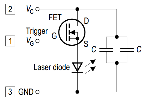
Some laser diodes have integrated switching FETs and capacitors for high-speed, high-power applications (such as laser range finding).
Pulse-Width Extending
A common use for an LED is to connect it to a digital output pin of a microcontroller/IC which goes active upon a certain event (say the microcontroller receives a packet of data).
The problem with this is that the length of time that the output pin is active for can be a really short amount of time, e.g. microseconds or even nanoseconds. It the events are rare enough, this may make it impossible to see the LED flicker.
One way to fix this with hardware to to use a simple pulse-width extender circuit as shown in This is a placeholder for the reference: fig-led-pulse-extending-circuit-schematic-annotated-rc-mosfet.
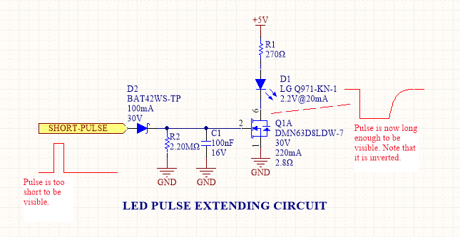
This circuit uses an RC network to form a time delay. When the short pulse arrives, the MOSFET is turned on almost immediately, and the LED lights up. When the pulse stops, the diode prevents the capacitor from discharging immediately, and instead has to discharge slowly through the resistor. The MOSFET/LED remain on until the voltage on the capacitor drops below the MOSFET’s gate-source threshold voltage (or something close to that).
Peak vs. Dominant Wavelength
LEDs are usually given with two different quantifiers regarding their wavelength, both the peak wavelength and the dominant wavelength.
Most LEDs emit a narrow spectrum of light (as opposed to filament-style bulbs, which emit a broad spectrum of light). The spectral shape is approximately Gaussian (a.k.a. the normal distribution).
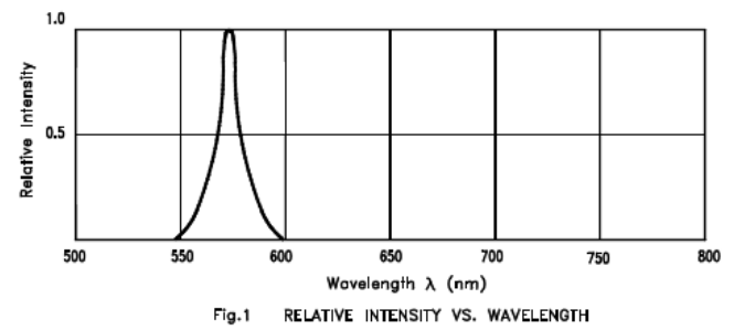
The peak wavelength is the wavelength at the peak of the spectral density curve. The dominant wavelength is a colorimetric quantity that describes the perceived colour of the LED with respect to the human eye. The human eye essentially sees a weighted average of all the wavelengths emitted by the LED, and perceives a single colour based on this averaging.
The dominant wavelength is important for user interface designers as it determines the “colour” the user perceives.
Converting Between uW/cm2 and PAR
Many grow lights (lights that provide a “fake sun” for plants to trigger photosynthesis, typically used in indoor growing environments) now use LEDs (sodium lamps were a popular choice before LEDs became both powerful and cheap enough). In these agricultural applications, you might have to convert between irradiance given in and PAR given in .
The Planck-Einstein equation gives a direct relationship between the frequency of a photon and its energy9:
where:
is the energy of the photon, in
is the Planck constant, 10
is the frequency of the photon, in
Of course you can use to write this in terms of the wavelength instead of frequency:
where:
is speed of light in a vacuum,
Knowing this, you can convert an energy from into a number of photons. One issue however is that the light from an LED is not emitted all at one precise frequency, it is usually spread across a small band of wavelengths known as its spectrum. One approximation is to just pretend all the light is emitted at peak wavelength. A more precise method is to take the spectrum, digitize it, and then calculate the proportion of photons for each small increment in wavelength.
So number of photons per second per meter squared, based on the irradiance (I’m not using here for irradiance as that will get confused with the energy in the Planck-Einstein equation) is:
We now need to convert from number of photos to number of moles, which we can use Avogadro constant for.
That is the basic equation done. But if we want to be lazy and not convert to SI units before punching the numbers in, we can compensate for this in the equation:
(the Planck constant), (the speed of light in a vacuum), and (the Avogadro constant) are all constants, so we can simplify them with the to:
Since we’re trying to make it easy, let’s put in units of instead of also:
If you use the equation before we compensated for the different popular units of for irradiance and for PAR, you can use also use this equation for radiance (e.g. output light power from an LED or collection of LEDs).
Basic UI Uses
LEDs are commonly used for basic user interface (UI) purposes in embedded systems.
Because of their simplicity, they are often a fall-back mechanism if there is no other form of error reporting available to the application at that time. For example, even if a microcontroller has a debug serial port and a LCD display for indicating errors during normal operation, there is still a few situations in where these would be unavailable:
- During the boot process, before the serial port and LCD are initialized.
- If the microcontroller is in a low-power mode, and the serial port and LCD are turned off.
- During an error condition such a segmentation fault. In certain errors you cannot rely on the firmware to work correctly (memory could be corrupted). Attempting to indicate this error to the user using the serial port of LCD may fail due to the driver code being corrupted. There is a much higher chance that writing to a single register to turn the LED on will work.
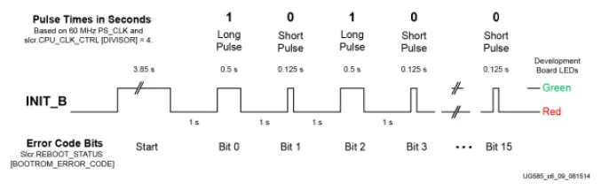
One example of this is the Zynq 7000 SoC’s BootROM. The BootROM is the basic code that runs on startup that loads the FSBL. To indicate an error, it toggles a pin high and low. It is designed so that you can connect an LED to this pin and see the error code. The waveform of the LED error code output by the Zynq 7000 BootROM is shown in This is a placeholder for the reference: fig-zynq-7000-bootrom-led-error-code-waveform.
LED Chemistries
Aluminium gallium indium phosphide (AlGaInP): Used for making high-brightness red, orange, yellow and green LEDs.
Gallium nitride (GaN): Used for making blue LEDs, and white LEDs by coating the blue LED with a phosphor which emits light across the visible spectrum.
Gallium phosphide (GaP): Used in the older green and yellow LEDs and had horrible luminous efficiency (around 0.1 lumens/W) which meant they were not very bright. Hewlett Packard referred to this colour as “emerald green”.12
Gallium arsenide (GaAs): Used for making infrared LEDs with a spectral peak at 950nm and a forward voltage drop of around 1.2V. Almost completely invisible to the human eye.12
Gallium arsenide phosphide (GaAsP): This chemistry was used to make the first yellow LEDs which achieved wide adoption. GaAsP was placed on a GaP substrate. They were not very bright, with a luminous efficiency of around 0.1 lumens/W. GaAlAsP yellow LEDs have a slightly better luminous efficiency of around 0.5 lumens/W, but InGaAsP yellow LEDs are the brightest.12
LED Manufacturing By Color
White LEDs
The most powerful white LEDs are made by coating a blue LED with a phosphor which re-emits the blue light in a spectrum from mid-green to mid-red. These LEDs had a higher colour temperature of 5000-8000 K, which can be described as a icy cold white. This colour can be considered “harsh” for domestic interior lighting, and warmer whites have been developed. These have colour temperatures of around 3500K, and are made by making the phosphor convert more blue light into yellow light.12
Packaging
You can get LED’s in a variety of SMD packages. Common SMD LED packages include the 0603 and 0402 chip packages.
Lifetime And Reliability
The expected lifetime and reliability is not typically given on standard-issue LED datasheets, mainly due to:
- Typical LEDs last so long that lifetime of any product they are used in is determined by other factors
- It is expensive and time-consuming to measure LED reliability
- Lifetime and reliability information is considered somewhat confidential
However, some LED manufacturers to give lifetime and reliability information. This is typically done for higher power, specific purpose LEDs such as powerful illumination LEDs (think streetlights, car headlights) or agricultural growing lights. The lifetime is typically expressed as a curve of power maintenance over time (in terms of hours the LED has been on for). Power maintenance is how powerful the LED is (in terms of light output power) compared to when it was new. Typical single-value lifetimes can be described as the number of hours until the LED light output power reduces to 70 or 50% of its initial output power (a 70 or 50% power maintenance).
A History of LEDs
In the 1970s, the first green LEDs became available. These were gallium phosphide (GaP) LEDs, and were not very bright compared to modern green LEDs (they had a luminous efficiency of around 0.1 lumens/W).12 Pure GaP LEDs emit light with a wavelength of 555 nm.13 If a green LED looks somewhat faint and yellow-green, it might be a GaP LED.14
Gallium aluminium arsenide (GaAlAs) LEDs became available in the 1980s, and offered significant brightness improvements over the GaP LEDs.15
In the 1990’s, aluminium gallium indium phosphide (AlGaInP, also AlInGaP, InGaAlP) LEDs were developed which allowed the production of ultra-bright red, orange, yellow and green LEDs. By adjusting the specific composition of the AlGaInP, the wavelength of the emitted light can be adjusted across the range from red to green (but not blue).16
The first commercially viable blue LED was developed by Shuji Nakamura (along with Isamu Akasaki and Hiroshi Amano) in 1992. It was a revolutionary breakthrough as it was one of the last colours yet available, and also allowed the creation of bright white LEDs (by using a blue LED and a fluorescent phosphor).17 They were awarded the Nobel Prize in Physics in 2014 for their work.18
Footnotes
-
Street Co. How Is Viewing Angle An Important Asset Of LED Displays. Retrieved 2022-06-19, from https://streetcommunication.com/how-is-viewing-angle-an-important-asset-of-led-displays/. ↩
-
Worldsemi. WS2812 vs. WS2812B. Retrieved 2024-01-13, from https://cdn.sparkfun.com/assets/learn_tutorials/1/0/5/WS2812B_VS_WS2812.pdf. ↩
-
Gryko, Lukasz & Blaszczak, Urszula & Zajkowski, Maciej. (2023). The Impact of Time and Temperature of Operation on the Characteristics of High-Power UVC LEDs and Their Disinfection Efficiency. Applied Sciences. 13. 12886. 10.3390/app132312886. ↩
-
Wikipedia (2024, Dec 31). Log reduction. Retrieved 2025-04-24, from https://en.wikipedia.org/wiki/Log_reduction. ↩
-
American Air & Water (2021). UV Irradiation Dosage Table [web page]. Retrieved 2025-04-24, from https://www.americanairandwater.com/uv-facts/uv-dosage.htm. ↩
-
Normand Brais. About PCO: Photocatalytic Oxidation [article]. Sanuvox. Retrieved 2025-03-10, from https://sanuvox.com/en/blog/about-pco-photocatalytic-oxidation/. ↩
-
Philips. Indoor Air Purification and Disinfection [article]. Retrieved 2025-03-10, from https://www.lighting.philips.com/application-areas/specialist-applications/special-lighting/purification-through-photocatalytic-oxidation. ↩
-
Namrata Pathaka, Oluwafemi J. Caleba, Cornelia Rauhc, Pramod V. Mahajan. Efficacy of photocatalysis and photolysis systems for the removal of ethylene under different storage conditions [article]. Elsevier. Retrieved 2025-04-24, from https://fn-nano.com/wp-content/uploads/2019/07/Ethylene-removal.pdf. ↩
-
Wikipedia (2022, Jan 15). Planck relation. Retrieved 2022-02-23, from https://en.wikipedia.org/wiki/Planck_relation. ↩
-
Wikipedia (2022, Feb 6). Planck constant. Retrieved 2022-02-23, from https://en.wikipedia.org/wiki/Planck_constant. ↩
-
AMD. Zynq 7000 SoC Technical Reference Manual (UG585). Retrieved 2024-08-19, from https://docs.amd.com/r/en-US/ug585-zynq-7000-SoC-TRM/BootROM-Error-Codes. ↩
-
Don Klipstein. LED Types by Color, Brightness, and Chemistry. Retrieved 2025-01-13, from https://donklipstein.com/ledc.html. ↩ ↩2 ↩3 ↩4 ↩5
-
Wikipedia (2024, May 2). Gallium phosphide. Retrieved 2025-01-10, from https://en.wikipedia.org/wiki/Gallium_phosphide. ↩
-
Strostkovy (username). Response to “I have two almost identical green leds but one is very dim while other one is very bright” [Reddit post]. Reddit. Retrieved 2025-01-10, from https://www.reddit.com/r/AskElectronics/comments/1hl00kz/comment/m3iqhlr/. ↩
-
Marktech Optoelectronics. The History of LEDs and LED Technology. Retrieved 2025-01-10, from https://marktechopto.com/the-history-of-leds-and-led-technology/. ↩
-
Illare. History of LED. Retrieved 2025-01-11, from https://illare.com/knowledge/history-of-led/. ↩
-
Lightology. Shuji Nakamura Blue LED. Retrieved 2025-01-11, from https://www.lightology.com/index.php?module=how_to&sub=shuji_nakamura_blue_led. ↩
-
Alexander Chilton (2014, Oct 10). Nobel Prize in Physics 2014: Why Were Blue LEDs so Hard to Make? [article]. Azo Materials. Retrieved 2025-01-11, from https://www.azom.com/article.aspx?ArticleID=11451. ↩