Low Power Design

Use High-Valued Resistors For Dividers
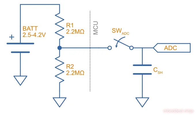
Even the innocuous resistor divider can draw too much current in low power designs if not careful. For example, let’s say you want to measure the voltage of the battery using an ADC with a reference voltage of 2.5V. The maximum battery voltage is 4.2V. You might choose to divide the voltage in 2 with a resistor divider consisting of a on top and bottom (very common values when low power is not a concern!). However, this will continuously draw from the battery (if at 4.2V).
You’ll need to up these resistors values, keeping the ratio the same. Generally values in the range are good. It’s easy to do mental maths using exponents to tell you that across draws (). So let’s replace the resistors with . Now we only have of current draw (at a battery voltage of , and the same output voltage. Great! But be careful, you must watch out for:
- Increased noise on the ADC input. Since the ADC input is being driven through a much high resistance, it’s more susceptible to noise. If noise becomes a problem, either adding a capacitor on the resistor divider output (more on this below) or averaging the readings in firmware can help!
- The input capacitance of the ADC can cause the voltage to sag during measurement. At the start of an ADC measurement, the ADC switches to the selected input (a single ADC peripheral can usually switch between a large number of pins). The ADC typically contains a sample-and-hold capacitor. When this capacitance is connected, it can cause voltage to sag as it charges up the capacitor1 . One solution is to add your own capacitor on the output of the resistor divider, which has a capacitance much larger than the internal capacitance (e.g. ).
You could aim to add enough capacitance so that when the internal capacitor is connected up, the voltage disturbance is at maximum 1 LSB of the ADC reading.
- The ADC input takes a long time to settle if the battery voltage changes quickly. This is most apparent if you have just connected the battery to the device, and the MCU powers up and measures the battery voltage. The MCU boot time is likely to be very fast compared to the RC time constant with resistors. Your MCU firmware might think the battery is flat, but in reality the ADC input capacitance is still charing up! You will have to add a delay in to only measure the battery after a delay on startup.
Use a SMPS Instead of a Linear Regulator
Linear regulators will not offer any power saving if the system runs of a voltage much less than the battery, as all the extra energy will just be burnt through the linear switch in the regulator. A SMPS however will perform voltage conversion using switched inductive and capacitive elements and typically give you 80-95% power efficiency from input to output.
However, you can’t just pick just any SMPS. You need to pick one which has a low quiescent current (). It is also a good idea to pick one with burst-mode. This is when the SMPS cycles between on and standby states when operating at low power. It greatly reduces the quiescent current draw of the SMPS.
Watch out for the feedback resistor network on your SMPS, if the values are too low the will draw a lot of current. Try and increase the resistance(s), but watch out for instabilities if the values are too large. The SMPS datasheet should guide you on this process. If it is specifically designed for low power operation then it will probably use appropriate resistor values in the first place.
Turn On LEDs Sparingly
A standard indicator LED consumes between 1-20mA when turned on. This is going to flatten most small batteries very quickly if left on. The good news is that humans can see very rapid pulses of light, so you can still communicate with the user with quick flashes.
The amount you can reduce the period of a flash is a function of brightness. The brighter the LED, the shorter you can make the pulse. For starters, try a pulse of around 10ms long and then make it shorter or longer until you can an acceptable level.
For pulses shorter than the flicker fusion frequency, the eye “sees” a brief pulse whose brightness is proportional to the luminous intensity multiplied by the ON time.
Use An Event Based Architecture in Your Firmware
In a low power product, you want the MCU to spend most of it’s time in a sleep mode. A MCU normally has different “levels” of sleep, depending on how many things are turned off and what it can wake up from. GPIO interrupts are your best friend, as they are normally supported right down to the deepest levels of sleep. Many ICs you might attach to a MCU via a comms bus such as I2C typically also have a few configurable interrupt lines. For example, a temperature sensor IC might allow you to set over and under temperature limits which cause the interrupt lines to change state. These can be directly connected up to GPIO on the MCU that support interrupts, and can be used to trigger a wakeup and perform an action. This is a much better approach for low power design than continuously polling the temperature over the I2C bus.
The Zephyr OS combined with Nordic chips supports low power operation out-of-the-box. Whenever one of your Zephyr threads is not doing anything, the MCU is automatically put to sleep.
Compile For Speed, Not Code Size
As mentioned above, for low power operation you want to spend as much time sleeping as possible. Another way to achieve that goal is to tell your compiler to optimize for speed rather than code size. In GCC and other similar compilers this is done by using the -O3 flag when compiling.
Executing Code from RAM Instead of Flash
Program code it typically executed from flash memory. However, since RAM is just a different memory address, there is generally no reason why code cannot be executed from RAM, as long as you copy the code to RAM on startup and setup the linker correctly. Executing code from RAM can provide two avenues for power savings:
- Executing from RAM is typically faster than flash, reducing the time the MCU is awake before it sleeps again.
- Executing from RAM can allow flash memory to be disabled (if your MCU supports this) to save power.
These options are not mutually exclusive, i.e. you may execute from RAM and see benefits from faster execution AND lower power consumption from the flash controller.
I have heard of this technique being used on ST Microelectronics STM32U5 and WCH MCUs.
Make Sure Digital Inputs Are In Defined States
Indeterminate (floating or otherwise not either high are low) voltages on digital CMOS inputs that are connected to the internal input buffers can cause the input circuitry to draw significant current. This is because a voltage in the middle of the range partially turns on both the N-channel and P-channel MOSFETs that form the input buffer. This causes shoot-through current to flow directly from VCC to GND.
To fix this, make sure you do one of the following:
- Make sure that all digital inputs that are connected to the internal input buffers will be in defined states during sleep. This can be done by adding pull-up or pull-down resistors to the inputs. Add a pull-up resistor if the default pin state is HIGH, and a pull-down resistor if the default pin state is LOW so that you are not drawing extra current.
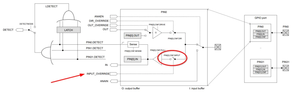
- Disconnected the input pin from the internal input buffer if your microcontroller supports it.
- Change the pin to an analog input (via firmware) during sleep. This achieves the same end result of disconnecting the CMOS input buffer and allows you to keep the pin floating if needed.
Measuring Power Consumption
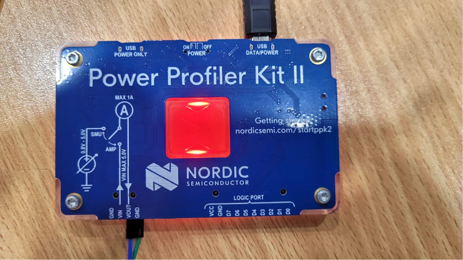
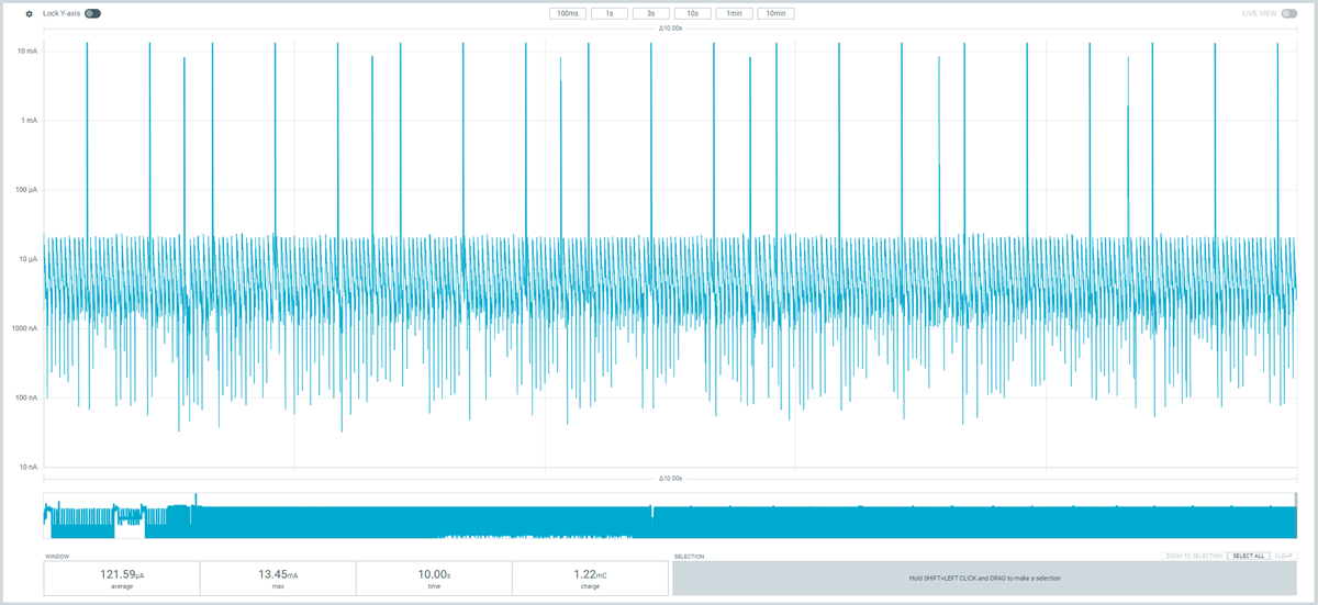
One of the difficulties of measuring low power circuits is that you often need a measurement device which has a very large dynamic range. Most low power circuits will draw something in the 1 to 10’s of microamps when sleeping, and then suddenly draw mA or amps for short durations when actively doing something. Most multimeters can measure microamps accurately, but will saturate when large currents are draw. Worse, they may not even permit a large current to be drawn, either due to a large measurement resistance or fuse being blown.
Footnotes
-
Ole Bauck (2016, May 23). Measuring Lithium battery voltage with nRF52. Nordic Semiconductor. Retrieved 2024-02-10, from https://devzone.nordicsemi.com/nordic/nordic-blog/b/blog/posts/measuring-lithium-battery-voltage-with-nrf52. ↩
-
Nordic Semiconductor (2024, Oct 1). nRF52840 - Product Specification - v1.11 [datasheet]. Retrieved 2026-01-26, from https://docs.nordicsemi.com/bundle/ps_nrf52840/page/keyfeatures_html5.html. ↩