Small-Signal Analysis
Small-signal analysis can be used to find the input/output impedances of various sections of circuitry.
Small-Signal Analysis Method
-
Find the quiescent point (DC operating point) of the circuit. Remove all signal sources, leaving the DC supplies, and find the DC voltages and currents at each node in the circuit.
-
Linearize the non-linear circuit components at the DC operating point. The most basic example of this is a diode, whose current is approximately proportional to the square of the voltage across it. But as long as the signal is small (hence the name, small-signal analysis!) compared to the DC operating point of the diode, you can approximate this to a linear relationship, i.e. . This resistance is called the dynamic resistance.
-
Find the small-signal solution: Now the DC sources are removed. Voltage sources are replaced with resistors (short circuit), current sources are replaced with resistors (open circuit). The signal sources are re-introduced and then finally node voltages and currents are solved using easy linear equations.
Taking it a step further: The complete solution is just the sum of the DC operating point + the small-signal solution.
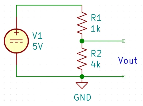
Analysis Of A Resistor Divider
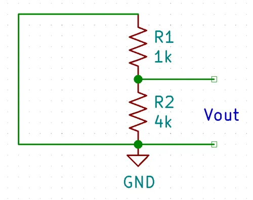
We assume Vin is a perfect voltage source, therefore we can replace it with a short.
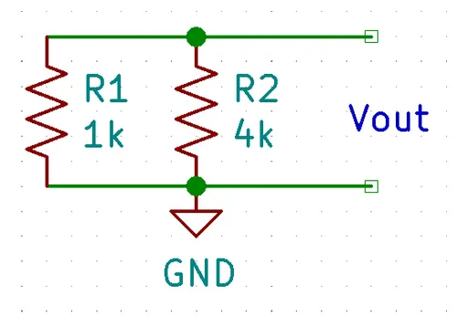
These two resistors are now in parallel, we can re-arrange the circuit as below to clearly show this:
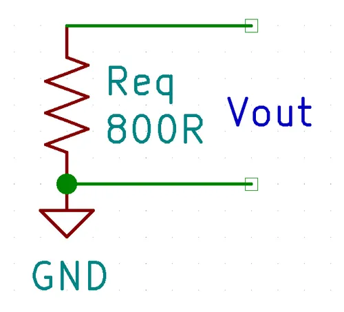
The two resistors in parallel can be replaced with a single equivalent resistor (remembering ):


