Decoupling And Noise Suppression

Bypass Capacitors
Bypass capacitors are used to separate AC and DC signals from one another. Normally they are used to short out the AC component of a waveform and allow through the DC signal. A common type of bypass capacitor is a ‘decoupling’ capacitor. This is usually a 100nF (or more commonly, 0.1uF) capacitor connected to the power and ground pins next to any digital or switching IC. It is placed as close as possible to the pins to give the maximum effect (reducing the loop area). It serves to reduce the high frequency AC components on the power lines generated from the Ic itself. Another common type of bypass capacitor is the low frequency bypass capacitor. These are used to reduce voltage sag on the power rails from high current pulses. When very large currents are being pulsed, an resistor or inductor is also used to form a RC or LC network.The value of the components used in a low-frequency bypass circuit depend on the magnitude and length of the current pulse.
Situations When You Must Consider Noise:
- High-gain, low input level amplifiers (e.g. pre-amps)
- High frequency circuits
- Circuits with large current pulses
- Circuits with sensitive sensors (this essentially means you will need a high-gain, low input level amp)
- Circuits in noisy (in the electrical sense) environments (e.g. car engine bays, next to power circuitry etc.)
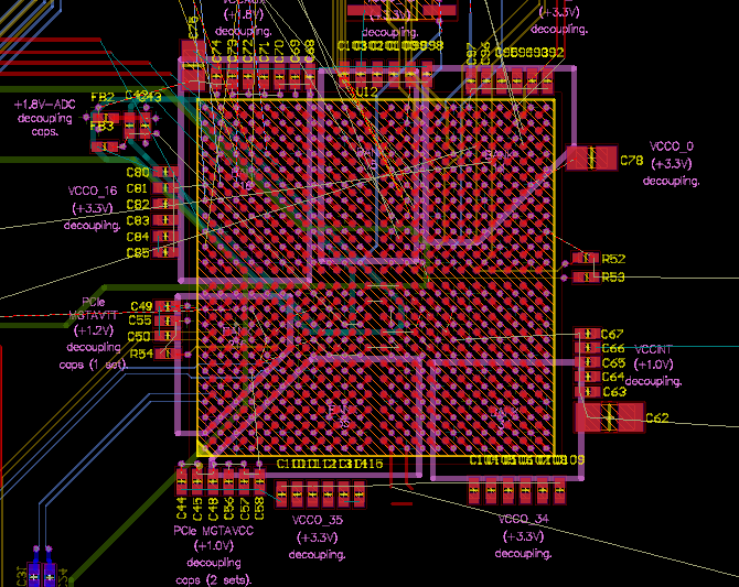
Note that top-side only components for high-speed FPGA designs is not recommended, and prototyping is definitely needed for design verification.
Noise From VFDs
In my experience, nothing emits more noise than a variable frequency drive (VFD). I have used the Teco 7300CV VFD to control a 750W, 230V induction motor. The VFD generated plenty of noise around the 24MHz range, which travelled down the ground and analog control wire to external circuitry that was setting the motor speed. I was using a basic 20MHz oscilloscope to measure the noise, and it was present even when the oscilloscope probe was connected to it’s own ground?!? Even when the oscilloscope was isolated (using a 12V inverter running from a lead-acid battery), this noise still showed up on the screen. To try and quench the noise, RC filters, LC filters, and even isolating transformers were employed, but nothing seemed to work. The noise levels seemed to be around 100-200mV peak-to-peak, with 2V spikes seen occasionally! Apparently, switching noise on the motor phase wires is capacitively coupled to the motor case. It has to return to the live input of the VFD (the source of the switching), which means it has to travel back down the motor cable shield, and then through earth’s chassis to the mains transformer