Switch Mode Power Supplies (SMPS)

Switch-mode power supplies (SMPS) are power conversion circuits that efficiently convert input voltages/currents (power) into different output voltages/currents by switching currents through inductors and capacitors.
There are many child pages covering the various SMPS topologies. If you want to:
- Decrease the voltage, see the Buck Converters page
- Increase the voltage, see the Boost Converters page
- Increase or decrease the voltage, see the Floating Buck-Boost page, or SEPIC page
- Increase or decrease AND invert the voltage, see the Inverting Buck-Boost Converters page
Unlike linear regulators which act as a dynamic series resistance to dump energy as heat and produce a lower output voltage, SMPSs efficiently perform voltage conversion by storing energy in the magnetic field of an inductor and electric field of a capacitor (and are not limited to just producing lower output voltages, they can produce higher output voltages also). While constant output voltage is the more common configuration, they can also be configured with constant current outputs (i.e. act as a current source) which is useful for things such as LED drivers.
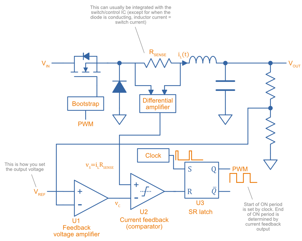
If you want to learn about the different SMPS control methodologies, e.g. voltage mode control or current mode control, see the SMPS Control Methodologies page
Child Pages
SMPS Modes Of Operation
SMPS can work in different modes of operation:
- Continuous conduction mode (CCM)
- Discontinuous conduction mode (DCM)
- Critical conduction mode (CrCM)
- Burst-mode
We’ll explain these a little in the following sub-sections before moving on to boost converters.
Continuous Conduction Mode (CCM)
Continuous conduction mode (CCM) is when the current through the inductor never falls to 0 during the switching cycle. In the case of converter with multiple inductors (e.g. [^SEPIC, SEPIC], [^Ćuk Converter, Ćuk Converter]), CCM is when the current never falls to 0 in any of the inductors.
For the same output current, the peak current through the inductor is lower when the SMPS is operating in CCM, compared on any other mode of operation.
CCM encounters turn-on losses through the switch. These can be exacerbated by the diodes reverse recover charge (). Ultra-fast diodes with low () are therefore recommended.
Discontinuous Conduction Mode (DCM)
Discontinuous conduction mode (DCM) is when the current through the inductor falls to 0 (and stays there for a period of time, if it just reaches 0 but does not stay there it is in [^Critical Conduction Mode (CrCM), Critical Conduction Mode]) during a switching cycle of the SMPS.
The switch (lets assume a MOSFET) is turned on at zero current, which means there is little turn-on loss.
Critical Conduction Mode (CrCM)
Critical conduction mode (CrCM) is at the boundary between CCM and DCM.
In CrCM, the peak inductor current is exactly twice the average value. This increases the switching element’s RMS current and turn-off current.
CrCM is good for low to medium power boost converter designs. At higher power levels the low filtering ability and high peak inductor currents start to become disadvantageous. Above this point boost converters operating in CCM are more preferable.
Burst-Mode
Burst-mode is a favourite for saving power when the load needs very little current. In burst-mode operation, the regulator operates for a period of time, charges up the output capacitor to a set threshold, and then shuts down completely. When the output voltage sags below a set threshold, the converter turns back on and the cycle restarts. This works well when there is little load current and so the converter can “sleep” for a significant period of time before it has to turn on again.
When the converter enters sleep, a number of power consuming components of the SMPS control circuit can be disabled (e.g. oscillators, voltage references, op-amps), saving power.
Advanced Asynchronous Modulation (AAM)
AAM is not supported by all buck converters, and is a mode used at low output currents to reduce the power consumption of the SMPS.
Ćuk Converter
The Ćuk converter is a buck-boost topology that only requires a single switch, but two inductors (just like the SEPIC). It also has the additional property of 0 output ripple current when it’s two inductors are coupled. It produces an output voltage which is opposite in polarity to the input (i.e. it is inverting).
Advantages:
- 0 output ripple current (when the two inductors are coupled).
Disadvantages:
- High current stress in the switch.
- Inverting (depending on the application, this could be an advantage!)