Termination

Termination is the process of adding components (usually resistors, but sometimes capacitors and inductors) to the ends of transmission lines (the start, the end, or both) to prevent things like reflections due to impedance mis-matches. A high-speed signal should ideally see the same impedance all the way from driver to receiver. The impedance of the transmission line is usually , but drivers are usually low impedance (), and receivers high-impedance (). For this reason, termination resistors are added at the driver and/or receiver to keep the apparent impedance equal to the characteristic impedance.
Types of termination:
- Series termination
- Parallel termination
- AC termination
- Thevenin termination
Most of these termination methods are discussed in the context of digital signals — i.e. fast transitions at the driver between two discrete voltage levels. Analogue signals can also be terminated.
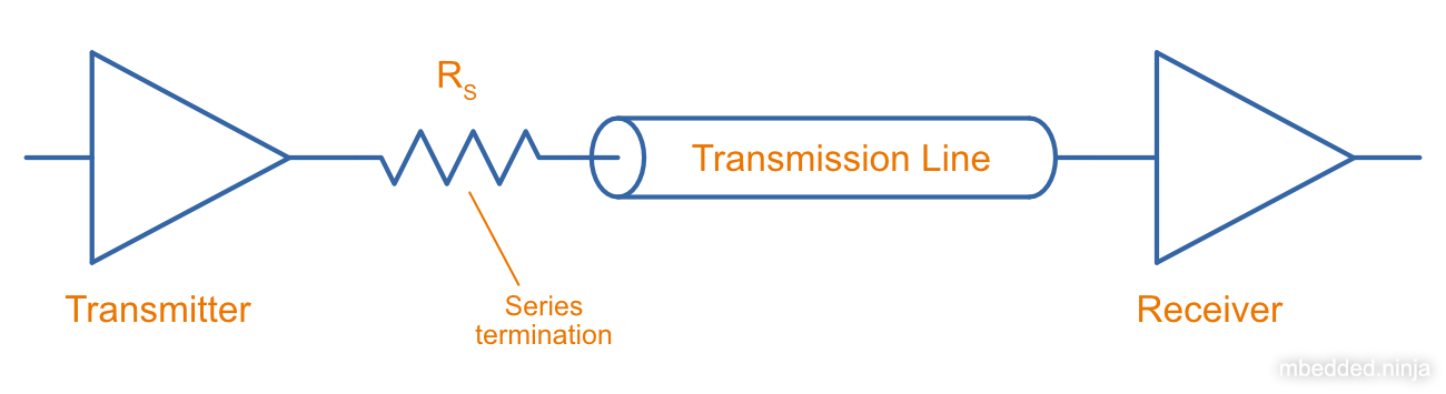
Series Termination
Series termination (a.k.a. back termination or source termination) is a termination method in where a resistor is added in series at the start of the transmission line, and no termination is added at the end of the termination line. Even though the start of the transmission line receives half the voltage from the driver, the receiver sees a perfect transition to the full voltage due to a purposeful reflection back to the driver.
Advantages:
- No DC loading on the transmission line.
- Receiver sees full driver voltage swing.
- Simple (only one resistor).
Taking The Driver Output Impedance Into Account
So far we have been assuming a perfect driver, i.e. one with no output resistance. Obviously in reality this is not the case, with the output impedance of most drive circuits being somewhere between . Luckily, as long as the output resistance of driver is less than the characteristic impedance of the transmission line, you can still use series termination. The idea is simple, just use the output impedance of the driver as part of the total series termination resistance.
where:
is the impedance, in
is the characteristic impedance of the transmission line, in
is the output impedance of the driver, in
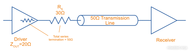
The below diagram shows a real-world example where the driver has an output impedance of , driving a transmission line. A series termination resistor is added to make the total series resistance equal to the transmission line’s characteristic impedance.
Series Termination Summary
- Consumes no power at steady-state, only during transitions.
- Uses only one resistor.
- Due to reflections, only good for point-to-point connections (not multi-drop) in where the cable propagation time is short relative to the bit period.
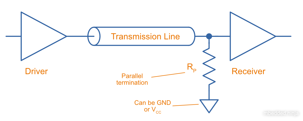
Parallel Termination
Parallel termination is a termination method in where a resistor is added to the receiver end of the transmission line, and is connected across the line and either GND or (hence in parallel).
The waveform exiting the transmission line needs to see the same impedance as the transmission line itself.
Typically, the input impedance of the receiver will be relatively high () in comparison to the impedance you’re aiming for:
And in which case the equation simplifies to:
Parallel Termination Summery
- No reflections (as opposed to series termination, which has one reflection back to the driver).
- Driver needs to provide continuous current for one of the logic levels.
- Good for point-to-point and multi-drop (e.g. RS-422, RS-485, CAN bus) connections.
- Bit period does not have to be much larger than cable propagation time.
- Lower noise margin than series termination (less voltage swing at the receiver)
Thevenin Termination
Thevenin termination is a form of termination in where two resistors (usually identical) are connected to the receiving end of the transmission line, one to and the other to .
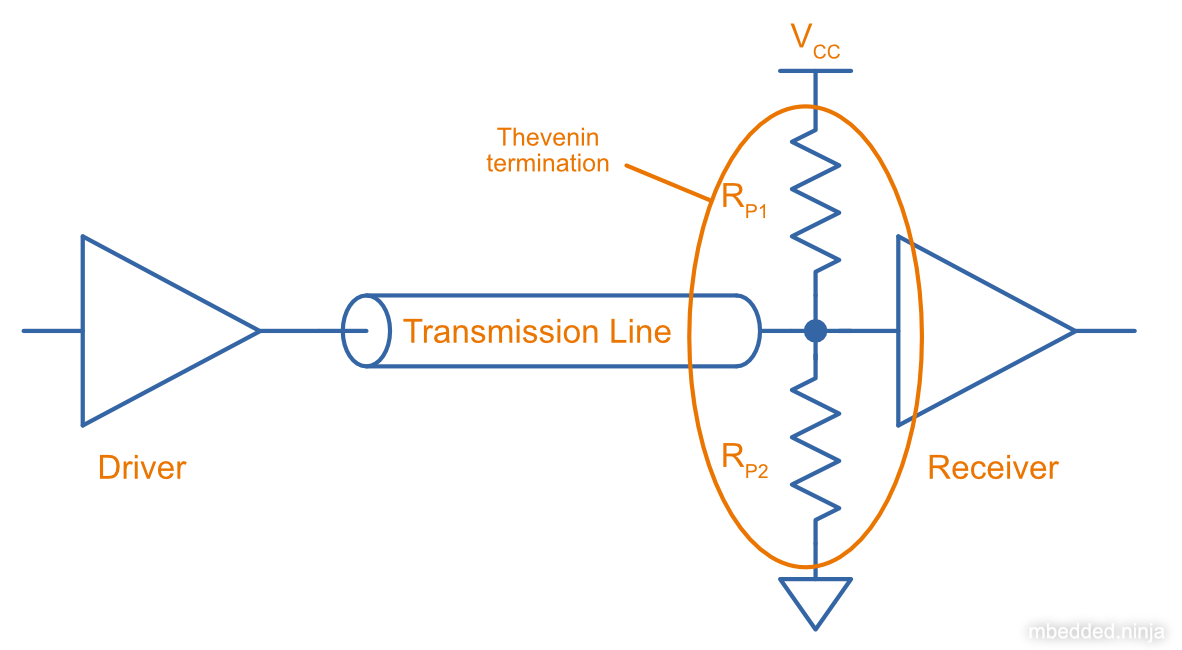
Assuming the receiver is relatively high impedance, the parallel combination of and must equal the impedance of the transmission line.
Thevenin Termination Summary
- Consumes half as much power as parallel termination, but still more than series termination.
- Uses two resistors, instead of the one each for series and parallel termination.
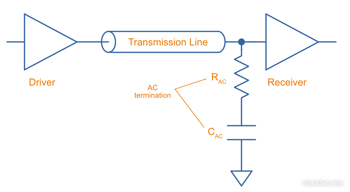
AC Termination
AC termination is similar to parallel termination, except a capacitor is added in series with the termination resistor at the receiver, as shown below. AC termination addresses the DC current consumption of parallel termination. The idea is that the resistor is still present to provide termination for the high-speed signals (which are fast enough to see the capacitance as low impedance), whilst the capacitor blocks DC current consumption1.
Footnotes
-
Ben Smith. Technical Information: AC Termination for Signal Buses. AVX. Retrieved 2022-01-31, from https://citeseerx.ist.psu.edu/viewdoc/download?doi=10.1.1.83.298&rep=rep1&type=pdf. ↩