General Purpose Diodes

General purpose diodes are just what they say they are — simple diodes with no special functionality, used for a wide range of rectification purposes.
Schematic Symbol And Designator
On schematics, general purpose diodes use the reference designator D (as do almost all types of diodes) and use the following symbol (most other types of diodes DO NOT use this symbol, they use slightly adjusted versions).

Some believe that the diode symbol originated from the drawing of a point contact crystal diode, an early form of diode made from crystal and metal, used in things such as “crystal radio” sets2.
Parameters
Maximum Continuous Forward Current
- Symbol: or
The maximum continuous current the diode can withstand, usually limited by overheating.
Average Rectified Forward Current
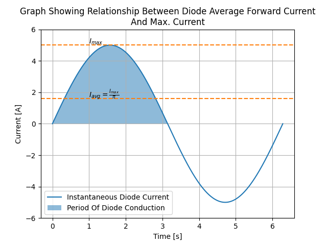
The average rectified forward current is the maximum average current the diode can sustain when it is only conducting during the positive half-cycle of a sine wave (i.e. working as a half-wave rectifier). It is related to the maximum current that the diode conducts at during the top of the positive cycle of the sine wave by . This equation is obtained by integrating the current over the positive half-cycle of a sine wave and then dividing it by the total time for one cycle:
This ignores the fact the diode doesn’t conduct until the forward voltage gets to about , which is fine to ignore in most cases as this part of the cycle will be tiny in comparison to everything else. The plot below shows graphically when the diode is conducting from a sinusoidal supply and the relationship between average rectified forward current and maximum (peak) current for a complete sine wave cycle. was chosen to be , and the waveform has a period of seconds for simplicity (although the relationship is independent of period/frequency).
Peak-surge forward current
- Symbol:
The forward current the diode can handle for a small amount of time. The exact time depends on the standard used to calculate this value (usually JEDEC). This is normally so you can determine whether the diode can handle inrush current/inductive energy pulses of a particular circuit.
Forward Voltage
- Symbol:
The forward voltage drop, usually rated at maximum continuous current (). An ideal diode would have no forward voltage drop. Schottky diodes have the lowest forward voltage drop of any diode. Generally, the smaller the forward voltage drop, the larger the reverse-leakage. The higher the temperature, the smaller the forward voltage drop. Typically 0.3-1.2V.
Reverse-leakage Current
- Symbol:
The leakage current when the diode is reverse-biased at the stand-off voltage. An ideal diode would have no reverse-leakage current. Generally, the smaller the reverse-leakage current, the larger the forward voltage drop. The higher the temperature, the higher the reverse-leakage current. Typically 10nA-1mA.
Peak Reverse Voltage
- Symbol: or 3
The maximum reverse voltage the diode can sustain without reverse breakdown occurring and possible damage. Sometimes called PIV (Peak Inverse Voltage).
Polarity
Most diodes have their polarity marked with a single line near the cathode (the “more negative” end when conducting current). They will let current flow from anode to cathode but not in the other direction.
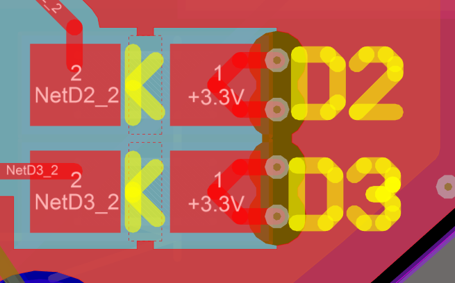
Diodes come in many component packages, one of the most common being the through-hole DO-41 package. They also come in standard SMD packages. It is a good idea to add polarity marks to the silkscreen layer on diode footprints. The picture below shows polarity marks being added to a diode with a 0603 footprint.
Can Diodes Share Current?
The short answer: No!
The slightly longer answer…
Diodes have a negative resistive thermal co-efficient, that is, as they warm up, their resistance decreases. This means that if you connect two or more diodes in parallel to share the current, one will heat up a bit faster than the other, start to conduct more, heat up even further, start to conduct even more, etc., until one is conducting almost all the current (and leading to thermal runaway!). This even occurs when the diodes are the same part number and from the same production run, due to the fact that there is always small differences between any two diodes. One way to prevent one diode from gobbling all the current is to add current-sharing resistors to each diode leg (called a ballast). They should be identical in resistance and have to drop at least (when the diode has a nominal voltage drop of around ) to be effective.
Bridge Rectifiers
Bridge rectifiers are 4 diodes connected in such a way that they rectify an AC voltage waveform into a DC one. The below schematic shows how a bridge rectifier is made from four diodes, and where the input AC and output DC signals are connected.

The image below shows a bridge rectifier being used after a transformer to convert (rms) into . Note that the frequency of the ripple will be twice the AC input frequency ().
Bridge rectifiers can have snubber elements attached to each diode. This helps reduce the high-frequency noise which can be induced when the diodes themselves switch on/off, due the leakage inductance and parasitic capacitance of the transformer (which cause oscillations when the diodes essentially change the output impedance). Typical values for the snubber circuit are a capacitor in series with a resistor.
Ideal Diodes
One of the main departures that any physical diode has from the concept of an ideal diode is its non-zero forward voltage drop. You can however compensate for this by making an ideal diode circuit from an op-amp and a diode. See Op-Amps - Ideal Diodes for more information.
Popular General Purpose Diode Part Numbers
1N400x Family
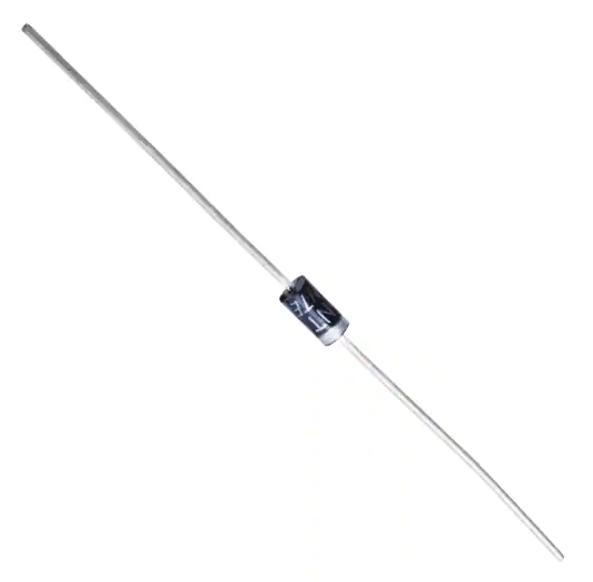
The 1N400x family of general purpose diodes have a forward current of 1A and reverse voltage ratings of 50-1000V. They come in the through-hole axial DO-41 package.
Specifications of the various diodes in the 1N400x family3:
| Part Num. | 1N4001 | 1N4002 | 1N4003 | 1N4004 | 1N4005 | 1N4006 | 1N4007 |
|---|---|---|---|---|---|---|---|
| Forward Current | 1A | 1A | 1A | 1A | 1A | 1A | 1A |
| Max. Reverse Voltage | 50V | 100V | 200V | 400V | 600V | 800V | 1000V |
Supplier Links
- DigiKey: Diodes - Rectifiers - Single
- Mouser: Diodes - General Purpose, Power, Switching
Footnotes
-
DigiKey. NTE Electronics, Inc 1N4007. Retrieved 2021-11-25, from https://www.digikey.com/en/products/detail/nte-electronics-inc/1N4007/11645794. ↩
-
Wikipedia. Crystal detector. Retrieved 2021-09-26, from https://en.wikipedia.org/wiki/Crystal_detector. ↩
-
Vishay (2020, Apr 29). 1N400x Datasheet: General Purpose Plastic Rectifier. Retrieved 2021-09-26, from https://www.vishay.com/docs/88503/1n4001.pdf. ↩ ↩2