

 NinjaCalc
Component Schematic Symbols and Designators

Component designators and schematic symbols are used to quickly identify components both on schematics and PCBs. They usually consist of a short acronym representing the type of component, followed by a unique number to distinguish it from other components of the same type (e.g. R3, R4, C3).
Over the years, many standards have been released that specify particular designator prefixes for component types. These include:
- Australian Standard AS1102:1995 (Graphical symbols for electrotechnology)
- IEC 60617
- IEEE 315-1975.
However, many schematic and PCB silkscreen designs do not strictly follow any standard (although the similarities are usually quite high). The following list shows non-standard specific, commonly used acronyms and the type of component they represent.
List of Common Component Designators And Symbols
Sorted by alphabetic order.
Antennas (ANT)
There are a number of different schematic symbols for an antenna, but they all look similar and should be easily recognizable. The designator E is also used, however ANT is my personal preference.
Designator(s):
ANT(recommended)E
Recommended schematic symbol(s):


Assemblies (A)
Separate assembly or sub-assembly (e.g. daughter board). I do not see this designator used much in practice (and I myself have never used it, for things such as GPS modules with an LGA footprint I have always used the designator U).
Recommended designator(s):
A
Batteries (BT)
The designator BT is commonly used for a battery. The schematic symbol shown below is typical for a battery, although sometimes the distinction between a single-celled and multi-celled battery is made. If the battery is single-celled, this can be represented by a symbol with only one pair of long/short lines (representing the two electrodes of the cell). If the battery is multi-celled, two pairs of long/short lines with a dotted line connecting them (representing many plates) can be used. I prefer to just use the below symbol for any battery type.
Recommended designator(s):
BT
Recommended schematic symbol(s):

Capacitors (C)
C is the recommended designator for capacitors (both polarised and non-polarised). Sometimes you will see VC used for a variable capacitor (these are not common). I recommend using two different schematic symbols, flat plates for a non-polarised capacitor, and one plate which is curved for a polarised capacitor.
Recommended designator(s):
C
Recommended schematic symbol(s):


Recommended parameters to show on the schematics:
- Capacitance (e.g.
10uF) - Voltage (e.g.
16V)
For special high tolerance (e.g. 1% or less) capacitors it can be useful to show the tolerance also.
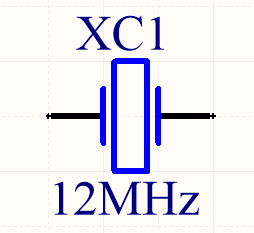
Crystals/Oscillators (XC, XTAL, Y)
Timing crystals. XTAL or Y are also used.
Recommended designator(s):
XC
Recommended schematic symbol(s):
Diodes (D)
The designator D can be used for most diodes. Sometimes Z is used for a Zener diode, and LED for a light-emitting diode, however TVS, Schottky and general purpose diodes are still just D.
Recommended designator(s):
D
Recommended symbol(s):


Ferrite Beads (FB, FEB)
Designator(s):
FB(recommended)FEB
Schematic symbol(s):

Recommended parameters to display on the schematic:
- Impedance (typically rated @ 100MHz)
- Max. current
Read more about ferrite beads.
Fiducials (FID)
Recommended designator(s):
FID
Recommended schematic symbol(s):

Fuse/Fuse Holders (F, XF)
F is the designator used for fuses (wired, electrical, etc.). XF is commonly used for a fuse holder.
Recommended designator(s):
F(fuse)XF(fuse holder)
Recommended symbol(s):

Gas Discharge Tubes (GDT)
Recommended designator:
GDT
Recommended schematic symbol(s):


Read more about GDTs.
Ground (GND, AGND, DGND)
Sometimes GND is used for all ground points, and sometimes grounds are split based on noise boundaries such as AGND and DGND (this is common in high-frequency circuits).
Designator(s):
GND: For general purpose use.AGND: Specialised analogue ground.DGND: Specialised digital ground.
Schematic symbol(s):


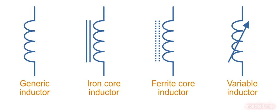
Inductor (L)
L is used as a designator for inductors. This is probably in honour of the physicist Heinrich Lenz who was a pioneer in the discovery of electromagnetism (and because I is commonly used to represent current).
Recommended designator(s):
L
Recommended schematic symbol(s):
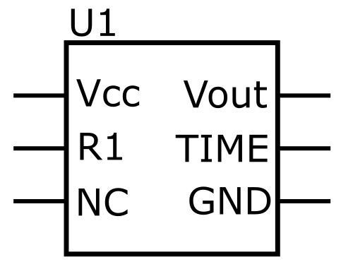
Integrated Circuits (U)
U is the designator for integrated circuits. ICs include microcontrollers, linear voltage regulators, op-amps, etc.
Why U? One theory is that U was the designator for anything “Unspecified”. It makes sense that when ICs first came into use that they would have been labelled as such. The name stuck, and now U is used for ICs (and no longer for anything “unspecified”). Another theory is that U stood for “Unrepairable”1.
In older schematics you may also see IC or Z used for integrated circuits.
Recommended designator(s):
U
Recommended schematic symbol(s):
Jack (J)
A jack/socket/female connector. Also defined in IEEE 315 as the least moving part of a connector set (which also includes a plug, P).
Recommended designator(s):
J
Jumper (JP)
Jumper or link (L is for inductor, not link). This maybe a simple piece of wire, a physical jumper component, or perhaps a resistor.
Recommended designator(s):
JP
Mechanical Part (MP)
A mechanical part. This is an umbrella term for many different things, such as screws, standoffs, brackets, etc.
Recommended designator(s):
MP
Motor (M)
Recommended designator(s):
M
Photovoltaics/Solar Panels (PV)
PV is the designator for photovoltaics (aka solar panels).
Recommended designator(s):
PV
Plug (P)
A plug/male connector. Also defined in IEEE 315 as the most moving part of a connector set (which also includes a jack, J).
Recommended designator(s):
P
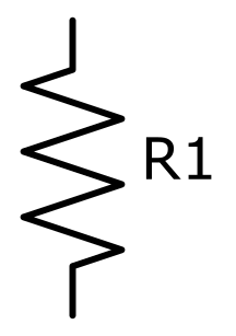
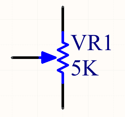
Resistors (R, VR)
Sometimes you will see LDR for light-dependent resistors. For more info see the Resistors page.
Recommended designator(s):
R: Standard 2-pin resistorsRN: Resistor networks (more than one resistor in the same package, sometimes sharing a common connection).VR: Variable resistors (aka potentiometers or rheostats). I have seen the reverse,RVused before, along withPOT.
Recommended schematic symbol(s):
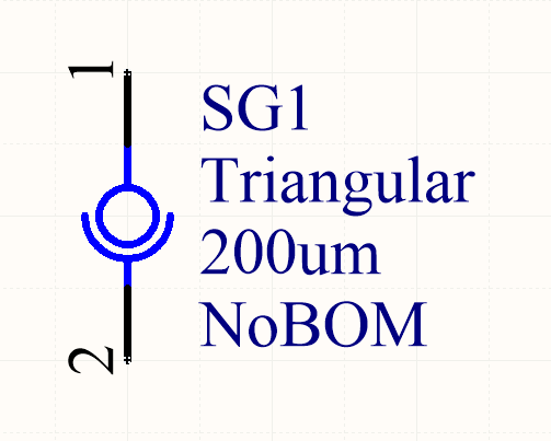
Spark Gap (SG)
Recommended designator(s):
SG
Recommended schematic symbol(s):
Switches (S, SW)
S is the designator used for a switch. SW is also commonly used. Sometimes you will see switches labelled according to their type (e.g. PB for push-button switches, DPDT for double-pole double-throw switches), but this is not recommended.
Recommended designator(s):
S
Test Point (TP)
Test point. These may be physical components on the PCB, or just places of exposed copper (e.g. pads, holes or vias).
Recommended designator(s):
TP
Transformer (T)
Designator(s):
T(recommended)TF(2)
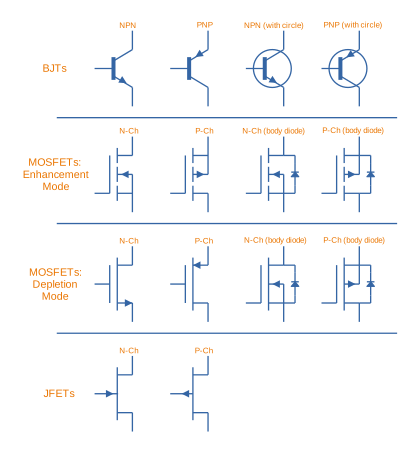
Transistors (Q)
Typically, Q is used for all transistors, no matter if they are BJTs, MOSFETs, JFETs, etc.
Designator(s):
Q(sometimesQis also used for an integrated circuit, but I prefer usingU)
Recommended schematic symbol(s):
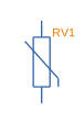
Varistors (RV)
Designator(s):
RV(recommended)
Schematic symbol(s):
Wire/Cable (W)
Wire/cable.
Recommended designator(s):
W
Regex
The regex pattern to match any valid component designator, which is one or more capital letters followed by one or more numerals, is:
^[A-Z][A-Z]*[0-9][0-9]*$The above pattern also contains the start and end-of-line anchors ^ and $, to enforce that there is no text before or after the designator. These can be removed if desired. More on using regex with component designators can be found on the Altium Scripting page.
Footnotes
-
Electronics Stack Exchange (2012, Jan 26). Why is “U” used for ICs on circuit diagrams? [forum post]. Retrieved 2019-05-03, from https://electronics.stackexchange.com/questions/25655/why-is-u-used-for-ics-on-circuit-diagrams. ↩
-
RF Cafe. AN (Army / Navy) Component Designators & Designations. RF Cafe. Retrieved 2021-07-06, from https://www.rfcafe.com/references/electrical/an-component-designators.htm. ↩