Zener Diodes

Zener diodes are diodes which have a specified reverse blocking voltage at which they breakdown and begin to conduct. They are similar to TVS diodes, but generally have a more defined and precise breakdown voltage, but a lower power rating. This allows Zeners to be used as shunt-style voltage regulators to power small circuits and as such, are sometimes called voltage regulator diodes. Shunt voltage references are similar in concept to zener diodes, except that they are more precise but can’t dissipate as much power.
Uses for zener diodes include:
- Low power/simple voltage reference
- Over-voltage protection for low power applications (use TVS diodes to dissipate high energy voltage spikes)
- To turn on a sub-circuit once a certain voltage level is reached (e.g. an LED in a simple battery charging circuit)
You can purchase Zeners with a reverse voltage drop as low as all the way to above . For voltage drops less than 1.8V, you can stack (i.e. place in series) multiple normal or schottky diodes in forward bias.
Schematic Symbol

How To Read A Zener Diode Datasheet
A zener voltage is given at a Zener test current . is the voltage the Zener regulates to. The test current is typically a current large enough to overcome the “knee” in the voltage vs. current curve, and put the Zener into its “voltage regulation” state (where the voltage stays relatively stable with large changes in current).
Regulation Performance And Dynamic Resistance
Low voltage (1-4V) Zener diodes are notoriously bad at voltage regulation due to their high dynamic resistance compared to their high-voltage siblings.
Simple Voltage-Limiting Circuit With A Zener Diode
You can build a simple voltage limiting circuit from a Zener diode, a NPN BJT transistor, and a couple of resistors. The schematic below shows an example of this, used to limit the maximum voltage to the pin of the ADP8140 LED driver IC.
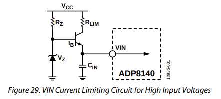
The voltage at is regulated to approximately . The current through is:
For more information, see the ESD Protection page.
Popular Zener Diodes
BZX55 Series
The BZX55 series of Zener diodes was (and still is) a popular choice for a standard through-hole Zener diode, provided in the axial DO-35 package. Manufactured by Vishay. Zener voltages range from 2.4V to 74V with a power dissipation of 500mW.1
BZX55 B 3V3Family --| | |Tolerance --------| |B=2%, C=5% |Zener Voltage --------|3V3=3.3V, 12=12VFootnotes
-
Vishay (2019, Mar 11). BZX55 Series Datasheet [datasheet]. Vishay. Retrieved 2021-09-25, from https://www.vishay.com/docs/85604/bzx55.pdf. ↩