

 NinjaCalc
Peltiers (Thermoelectric Coolers)

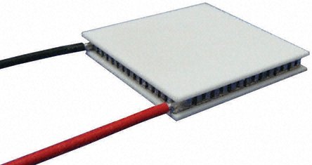
Peltier devices are electrical components that use the Peltier effect to heat/cool objects. They act as a heat pump, moving heat energy from the cold side to the hot side.
History
The Peltier effect was discovered by Jean Charles Athanase Peltier in 1834.
Uses
Peltier devices are used in things such as:
- Portable fridges/freezers (especially when powered from 12V)
- Electronic temperature stabilisers (e.g. CPU cooler)
- Temperature-sensitive scientific equipment
- Medical devices
- Photonic systems
Construction
Most Peltier devices consist of many small semiconductor junctions, joined together in an array, and connected between two thermally conductive, white ceramic plates.
Important Parameters
Max. Heat Transfer (Qmax)
The maximum heat transfer (also known as , or maximum work), is the maximum amount of energy per second that the Peltier device can move from the cold side to the hot side. It is measured in Watts ().
This always occurs when the temperature differential between the hot and cold sides is 0°C. (i.e. at the same temperature). Obviously, for any real-life operating Peltier device, this is impossible. The larger the temperature differential, the less heat can be moved across the plates.
is also dependent on the absolute temperature of the plates. As the absolute temperature rises, also increases. The absolute temperature that is measured at is usually specified on the Peltier device’s datasheet. The absolute temperature of the hot side is usually given (). Since is given for when both sides are at the same temperature, this is also equal to the temperature of the cold side.
It is important to NOT confuse the heat transfer with the input power .
Max. Temp Differential
The maximum temperature differential () is the maximum temperature difference that the Peltier device can produce between the hot and cold sides. It happens to be the point at which (remember that the maximum heat transfer decreases with increasing temp. differential). It also occurs when the Peltier device is being driven at maximum voltage and current.
For all practical designs is a theoretical upper limit, you will never be able to achieve this temperature differential.
Max. Operating Temp
The maximum operating temperature () is the maximum temperature any part of the Peltier device is allowed to reach. Naturally this is the maximum temperature of the hot side.
Do NOT confuse this with the maximum temperature differential, .
Be very careful not to exceed the maximum operating temperature! Among other things, you could cause the solder connecting the thermoelectric pairs inside the Peltier module to melt, destroying the device (and potentially causing short-circuits). This solder usually melts around 120-160°C.
How Should I Drive One Of These?
If you want simple on/off control and the hot/cold sides don’t need to switch, then you can control a Peltier device with a single mechanical switch, relay, or transistor (e.g. MOSFET).
If you want tighter control over the power, you can use PWM with an LC filter to smooth out the voltage. However, don’t connect raw, unfiltered PWM directly to the Peltier device, as this can cause excessive heating due to the RMS current (which is responsible for parasitic Joule heating) being higher than the average current (see Why Raw PWM Hurts A Peltier below).
If you want full control over the heat direction (i.e. which side is hot/cold), then you will need an H-bridge setup (similar to what is used to control stepper motors).
Why Raw PWM Hurts A Peltier
It’s tempting to drive a Peltier device by connecting a PWM signal straight to a transistor and switching the full supply across the device. This works, but it’s inefficient and reduces the achievable cooling. The reason comes down to the fact that the two competing effects inside a Peltier device scale differently with current.
The useful heat pumped from the cold side is proportional to the average current:
But the parasitic Joule heating (, half of which leaks back to the cold side and works against you) is proportional to the RMS current squared:
For a PWM waveform at duty cycle switching between and :
Taking the ratio of the RMS heating term to what you’d get from smooth DC delivering the same average current:
So for the same average (cooling) current, raw PWM dumps more heat into the device than smooth DC by a factor of (so it’s worse at smaller duty cycles). That extra internal heating directly eats into the net cooling and lowers the achievable . Note that increasing the PWM frequency does not fix this; the device responds to the actual current waveform, so the RMS penalty persists no matter how fast you switch.
This is borne out experimentally. Texas Instruments ran a head-to-head test driving a Peltier module with of constant current versus unfiltered PWM (a peak, 50% duty cycle waveform giving the same average, at ). The constant-current drive achieved a temperature differential greater than the PWM drive, making it 39.2% more efficient, and they concluded that “constant current drive is definitively preferred over PWM drive”.1 Note this matches the maths above: at the RMS heating term is times larger than for smooth DC at the same average current.
The accepted practice is to keep the current ripple below ~10% — TEC module manufacturers publish similar guidance, with Ferrotec recommending a maximum of 10% (preferred less than 5%) and Marlow noting that a ripple factor of less than 10% results in less than 1% degradation in .2 You achieve this by following the PWM stage with an LC filter so the Peltier sees near-DC current — exactly the same reasoning as for a buck converter. With proper filtering, PWM is an efficient and perfectly valid way to drive a Peltier, and is how most modern bidirectional TEC drivers work (a PWM H-bridge followed by an LC filter).
Examples
Many non-branded, cheap Peltier modules use the part number TEC1-127xx, where xx can be things like 03 or 05 (e.g. TEC1-12703, TEC1-12705). Be warned though, Peltier devices with identical part numbers in this style can have widely varying parameter values.
Footnotes
-
Olivier Mellin, Florent Muret (2020, Jan). Driving a Peltier Element (TEC): Efficiency and Aging [application report]. Texas Instruments. Retrieved 2026-06-25, from https://www.ti.com/lit/an/slua979a/slua979a.pdf. ↩
-
Meerstetter Engineering GmbH. Peltier Element Efficiency [website]. Retrieved 2026-06-25, from https://www.meerstetter.ch/customer-center/compendium/71-peltier-element-efficiency. ↩