Protecting IO Lines From ESD

This page explains some of the ways you can go about protecting IO lines on a PCB from ESD events. This page assumes a basic scenario, you are wanting to protect an IO line that comes from an external connector and then connects to a GPIO pin on a MCU. The MCU is running from a +3.3V rail voltage (). However, the examples also apply to pretty much any IO line that connects to some sort of sensitive IC circuitry, e.g. enable pins on PSU ICs, communication lines, etc.
A Simple Resistor
One of the simplest ways of protecting an I/O line from ESD is to add a series resistor, as shown in the schematic below:
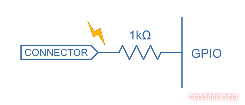
One thing to be aware of is that this will limit the maximum frequency that can be used through this IO line (more so than other ESD techniques, such as steering diodes as discussed below). The series resistor will form a low-pass RC filter with the parasitic capacitance on the line after the resistor. For short PCB traces, most of this parasitic capacitance will be from the input capacitance of the GPIO pin on the MCU. Something in the region of can be expected, which with a resistor will form a low-pass filter with a cut-off frequency of .
- Simple.
- Not terribly effective.
- Not suitable for high-frequency signals.
Resistor With Capacitor
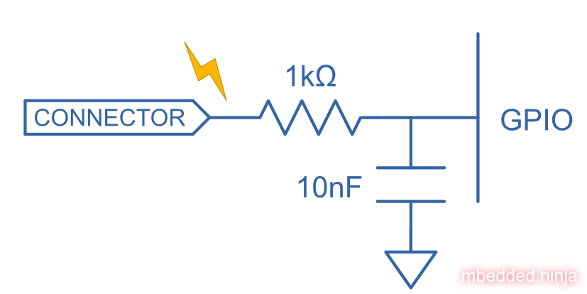
To improve on the simple series resistor, a capacitor can be added to further improve ESD protection. The capacitor is between the I/O line (once it has passed through the resistor) and ground. This forms a low-pass filter which will help quench short (high frequency) ESD spikes.
Advantages:
- Still pretty simple.
- Better than just a resistor.
Disadvantages:
- Not suitable for medium to high-frequency signals (even worse than just a resistor at attenuating high-frequency signals!)
TVS Diode
Another popular way of protecting an IO line from ESD is to connect a TVS diode to it. TVS diodes are designed to be operated whilst reverse biased and have preset reverse standoff voltages, above which point they begin to conduct and absorb energy. They are designed to be robust and able to absorb energy (which they dissipate as heat) from ESD events.
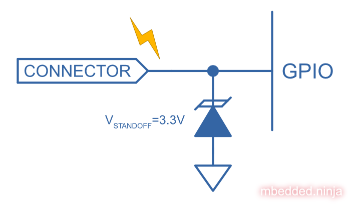
The above schematic is a unidirectional TVS diode, which will clamp a positive ESD event as the voltage starts to rise above , and will clamp a negative-going ESD event when the voltage gets to around and forward biases the diode.
Advantages:
- Simple
- Moderately effective
- No energy is dumped into voltage rails (as is with steering diodes), instead it’s absorbed by TVS.
Disadvantages:
- Voltage can still climb quite high
Steering Diodes
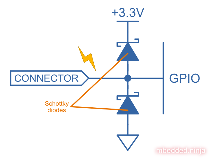
Steering diodes are connected between the I/O line and two voltage rails, typically and . You normally want to use Schottky diodes, as they have a lower forward voltage drop of around 0.3V compared to the standard PN junction diode forward voltage drop of 0.7V. This means your more robust external steering diodes will conduct and shunt more of the ESD energy away before the internal ESD protection diodes connected to the GPIO port in the MCU port do.
- Sharper turn on than a TVS diode.
- Dump energy into rails, which may be a bad thing.
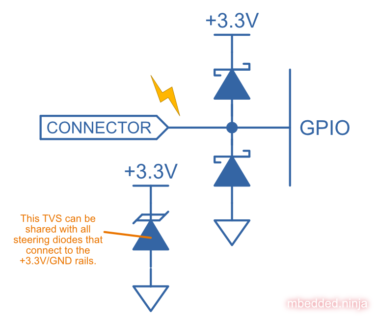
Steering Diodes And TVS
As we learnt above, steering diodes dump the ESD energy into the voltage rails. This can be OK in the following conditions:
- ESD energy is low
- ESD event is short
- There is some capacitance on your voltage rails (decoupling caps and PSU output capacitors count!).
- The circuits connected to your voltage rail consume a “bit” of power, i.e. are not ultra-low power design circuits which only draw 10 µA.
You start to run into problems if the ESD energy is high, and the ESD event continues for some time, and your voltage rail can no longer “absorb” the ESD (by consuming the energy with running circuits, or dumping it into capacitance). The voltage rail may start to climb. If you are using a SMPS or series linear regulator to power this rail, there is nothing that these devices can do to stop the voltage from climbing (remember they can only source current, not sink it — shunt regulators are the exception!). The rail voltage may climb to dangerously high levels which causes damage to the ICs running off it.
To add further protection, a TVS diode can be added to the voltage rail, to help clamp the voltage if it starts rising, as shown in the schematic below:
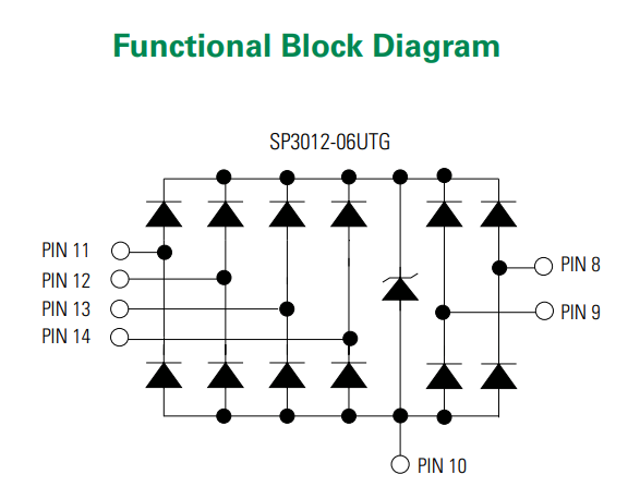
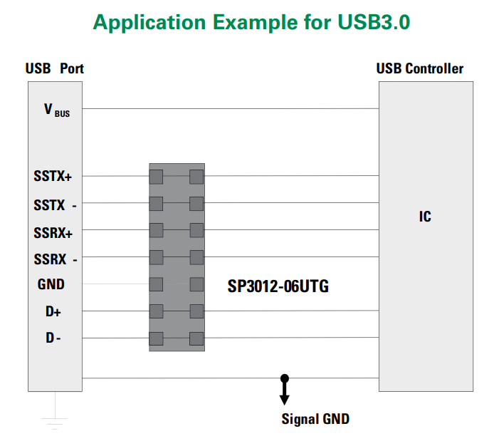
Some ESD diode arrays incorporate steering diodes and a TVS diode to do just this. For example, the Bourns CDDFN10-0506N features 6 steering diode pairs connected to a single TVS. It is designed for high-speed signals and presents an input capacitance of only 0.25-0.35pF to the signal line, as well as “feed-through” routing design to minimize impedance changes.1 Another example, shown below, is the SP3012-06UTG ESD diode array from Littelfuse.2 It is designed to protect USB3.0 data lines:
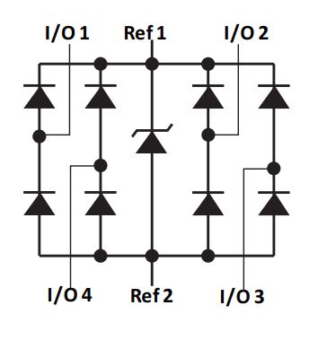
Another example is the Littelfuse SRDA3.3 steering diode array IC. It is designed to protect +3.3V IO lines and is rated to contact, air via IEC61000-4-2.3 Its functional block diagram is:
Isolation
TODO: Add info.
Footnotes
-
Bourns. CDDFN10-0506N - TVS/Steering Diode Array [datasheet]. Retrieved 2022-04-27, from https://www.bourns.com/docs/Product-Datasheets/CDDFN10-0506N.pdf. ↩
-
Littelfuse (2021). SP3012 Series: 0.5pF Diode Array for USB3.0 [datasheet]. Retrieved 2022-04-29, from https://www.littelfuse.com/~/media/electronics/datasheets/tvs_diode_arrays/littelfuse_tvs_diode_array_sp3012_datasheet.pdf.pdf. ↩ ↩2 ↩3
-
Littelfuse (2013). SRDA3.3 Series 8pF 35A Diode Array [datasheet]. Retrieved 2022-05-17, from https://www.littelfuse.com/~/media/electronics/datasheets/tvs_diode_arrays/littelfuse_tvs_diode_array_srda3_3_datasheet.pdf.pdf. ↩ ↩2