H-Bridges

An H-bridge is a two-leg/four-switch power inverter which converts DC current into a form of AC current. It is also known as a full-bridge. A half-bridge is only one leg of the full-bridge.
Adding a third-leg creates an inverter, which is commonly used to convert DC to 3-phase AC for high-power applications. With three legs, it has the benefit of reduced harmonics compared to a full-bridge.
Basic H-Bridge Circuit
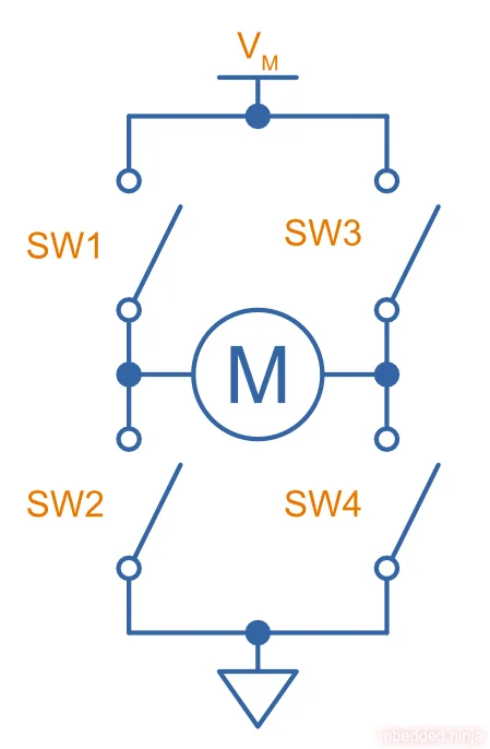
The image below shows the basic concept behind an H-bridge. Four switches (typically implemented as BJTs or MOSFETs) are arranged in two legs, with each side of the motor connected in the middle of each leg. By turning on various switches, you can apply voltage/current of either polarity to the motor, as well as make the motor open-circuit or short-circuit (which are useful for coasting and braking purposes).
The image below shows the four basic modes of operation you can achieve by turning on and off various switches in the H-bridge. With SW1 and SW4 closed, the supply voltage is applied across the motor in the positive direction and it spins “forwards” (forwards being an arbitrary direction depending on the motor windings). With SW2 and SW3 closed, the supply voltage is reversed across the motor, and it spins in the “backwards” direction. With all switches open (or any one switch closed) the motor is open-circuit and will “coast”, only slowing down due to friction and the load it’s connected to. With SW2 and SW4 closed, the motor is short-circuited and will brake, coming to a stop quickly.
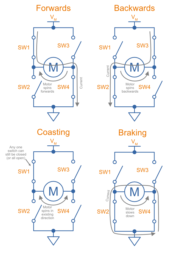
There is another form of braking which is even faster than shorting the motor out, and that is applying the supply voltage of the reverse polarity to the motor (i.e. trying to drive the motor backwards while it is going forwards).
H-Bridge Built With Transistors
Almost all serious half or full-bridges use MOSFETs as the switches. This is because MOSFETs have a very low on resistance, meaning they can sink/source plenty of current without heating up. Some of the better MOSFETs are pushing on resistances () as low as or less, allowing for continuous currents in the hundreds of amps as long as the MOSFET is heatsinked correctly.
For the same price and physical size, N-channel MOSFETs generally have lower on resistances than P-channel MOSFETs. For this reason in many H-bridges the top two P-channel MOSFETs are replaced with N-channel MOSFETs, with the one disadvantage that charge pump circuitry is required to drive the gates higher than the supply voltage when turning them on (more on this below).
Discrete Component H-Bridge With Only Two Control Lines
With a bit of clever circuitry, you can create a H-bridge made from discrete components that only requires two control lines, direction and PWM.
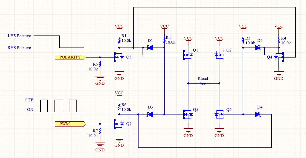
As a bonus, it also has shoot-through protection!
One thing to watch out for here is the forward voltage drop of the diodes compared to the gate turn-on voltage of the N-channel MOSFETs. The gates of Q5 and Q6 are driven low through diodes. This means that the voltage at the gate doesn’t go all the way down to 0V, but hangs around the forward-voltage drop of the diode. For general purpose diodes, this can be around 700mV, which is approaching the turn-on gate threshold voltage of some N-channel MOSFETs. The best solution is to use Schottky diodes (as shown), which have a lower voltage drop of around 300-500mV (dependent on current of course).
Driver ICs
There are heaps of H-bridge related ICs! Some are just a controller that takes in a PWM signal and outputs control signals designed to go to a MOSFET driver, some include the controller and the MOSFET driver, and some even include the power MOSFETs (these are typically called fully integrated motor driver ICs).
As mentioned above, top-side N-channel switches require a voltage greater than at the gate to turn them on. Most H-bridge drivers have an internal charge pump which takes care of this for you.
There are a few commonly used control methods:
- PWM IN1/IN2: Two PWM signals, one for each leg of the H-bridge.
- PH/EN: Provides a phase and enable signal, allowing for a speed and direction style interface. This interface only needs one PWM signal from the controlling MCU, vs. two for the PWM IN1/IN2 interface. The PH signal can be a standard MCU GPIO output, and the EN is connected to the PWM output.
- Half-bridge: Allows for independent control of each half-bridge.
L298/L298N
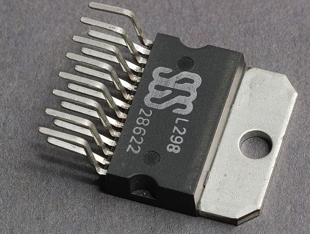
The L298 is an older (and now mostly obsolete), fully integrated motor driver IC that uses BJTs rather than MOSFETs for the H-bridges. It contains 2 independent H-bridges. It uses AND gates to implement simple control logic based two input lines and 1 enable line per H-bridge.
DRV8xxx
The DRV8xxx is a family of fully integrated (control and power electronics) brushed DC motor controllers from Texas Instruments. A P is added after the DRVxxxx (e.g. DRV8212P) to indicate it supports only the PWM IN1/IN2 interface and not PH/EN nor half-bridge mode.
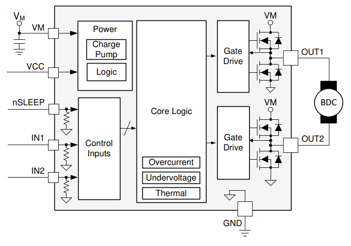
The below image shows the functional block diagram for the DRV8212P motor driver IC. It has internal charge pumps for the gate drives to power the high-side N-Channel MOSFETs, and basic over-current, under-voltage and over-temperature protection. There are two separate power supplies can be provided. is for the logic and can range from 1.65-5.5V. is purely for powering the motor and can range from 0-11V.3
The table below summarizes the key parameters for a number of parts in the DRV8xxx family.
| Part Number | (HS+LS) | Interface | Sleep | Package | Comment | |||
|---|---|---|---|---|---|---|---|---|
| DRV8210P | 1.65-5.5V | 0-11V | 1.76A | IN1/IN2 | nSLEEP pin | WSON-8 | ||
| DRV8212 | 1.65-5.5V | 0-11V | 4A | IN1/IN2, PH/EN, Half-bridge | Only the DSG package allows for the 3 different interfaces. | |||
| DRV8837 | 1.8-7V | 0-11V | 1.8A | IN1/IN2 | nSLEEP pin | WSON-8 | ||
| DRV8838 | 1.8-7V | 0-11V | 1.8A | PH/EN | nSLEEP pin | WSON-8 | Same as the DRV8837 except it has PH/EN interface. |
Bi-Colour LEDs
Bi-colour LEDs that only have two pins (two LEDs connected head-to-tail) require a full-bridge to be driven correctly. Normally the bi-colour LED can be connected directly up to pins on a microcontroller (with a current-limiting resistor), as long as the micro can sink and source the required current.
Filtering
Unfiltered H-bridges subject the load to a square wave whose frequency is the same as the frequency of the H-bridge switching elements.
This is acceptable for some loads (e.g. resistive heaters), but not for others (e.g. peltiers). The problem is that although the average power delivered to a load from a PWM controlled H-bridge is the same as powering the load from a continuous DC source at the average voltage, resistive losses are proportional to the square of the current ().
This results in higher resistive losses in a complex load controlled by a PWM source than a constant DC power source providing the same average input power.
The solution is to filter the switching H-bridge output, so the load sees a constant DC voltage. H-bridges can be filtered with two inductors and two capacitors, forming two low-pass filters on each side of the load.
External Links
http://homepages.which.net/~paul.hills/SpeedControl/SpeedControllersBody.html is a really good site explaining half-bridges, full-bridges and regenerative braking.
http://www.homofaciens.de/technics-base-circuits-h-bridge_en_navion.htm has some great general information and schematics on full-bridges.
Footnotes
-
Wikipedia (2023, May 15). H-bridge [wiki]. Retrieved 2023-07-19, from https://en.wikipedia.org/wiki/H-bridge. ↩
-
Texas Instruments. Motor drivers [product family page]. Retrieved 2023-07-18, from https://www.ti.com/motor-drivers/overview.html. ↩
-
Texas Instruments (2021, Jul). DRV8212P - 11-V H-Bridge Motor Driver with PWM Interface and Low-Power Sleep Mode [datasheet]. Retrieved 2023-07-18, from https://www.ti.com/lit/ds/symlink/drv8212p.pdf. ↩ ↩2