How To Calculate Maximum Track Current

All tracks (a.k.a. traces) on a PCB have a maximum current limit. For most of the PCB routing process, the PCB designer does not have to worry about this, as most tracks are far larger than than they need to be to carry the tiny currents associated with digital and analogue signals (i.e. the track width is limited by manufacturing tolerances rather than the maximum current it can take).
However, the track current limits do sometimes play an important rule when it comes to sizing power supply traces, motor driver circuitry, mains power circuitry and other tracks which take higher currents.
Wait, What Is A Maximum Current Anyway?
You may be wondering what is meant by maximum current. Is it the maximum current before the track “explodes” and spews plasma across the room? Is it the maximum current before the track slowly heats up, starts smoking, and eventually goes open-circuit?
In the interests of circuit board longevity, the “maximum current” is usually specified and neither of the above, but rather the is the current required to raise the temperature of the track a certain amount above ambient. This keeps the track temperature at a safe level which is not going to damage itself (unlikely) or the circuit material it is printed onto (more likely as the fibreglass material will decompose/start smoking before the copper starts melting).
What Standard Should I Use?
There are two dominant standards in use when it comes to calculating track current.
IPC-2221A
The first standard, IPC-2221A is quite old, and is based of an older standard called IPC-D-275, which is itself based of measurements and graphs drawn in 1954.
IPC-2221A has a single graph (currently figure 6-4), which the following equation for calculating the track current is derived from:
where:
= 0.048 for external traces, 0.024 for internal tracks
= the change in temperature (temperature rise) in
= 0.44
= cross-sectional area in
= 0.725
The standard only covers values where the current is 0-35A, track width is 0-10.16mm, temperature rise is from 10-100°C, and the copper from 0.5-3oz (which influences the cross-sectional area). Values outside this range are extrapolated (and there more error-prone).
This equation also assumes the track is sufficiently long enough the the end-points do not have a significant effect on the heatsinking. For example, this calculator should not be used for calculating the width of thermal-relief style connections from a copper pour to a via, in where the track is very short (0.2-1.0mm). It also assumes there are no vias along the length of the track.
The current in assumed to be constant (DC). However, you can use the RMS value for a pulsed current as long as the pulses are fast enough.
The temperature of the PCB material should NEVER exceed the relative thermal index (RTI) of the material. This is defined in UL746B as the temperature at which 50% of the materials properties are retained after 100,000 hours.
IPC-2221A Track Current Calculator
35um). Inputs highlighted amber are outside the range the IPC-2221A chart covers, so the result is extrapolated and less reliable.IPC-2152
The second standard, IPC-2152, is a much newer standard. It has a more technical and presumably accurate method for calculating the maximum track current.
History
The data in the IPC-2152 standard is based of the work of Mike Jouppi of Lockheed Martin, which was verified with a parallel study done by the Naval Surface Warfare Center, Crane Division. The results from these two experiments was compiled into IPC-2152 under the heading “Standard for Determining Current Carrying Capacity in Printed Board Design”1
The Calculation Steps
Unlike IPC-2221A, IPC-2152 is not just a simple equation.
-
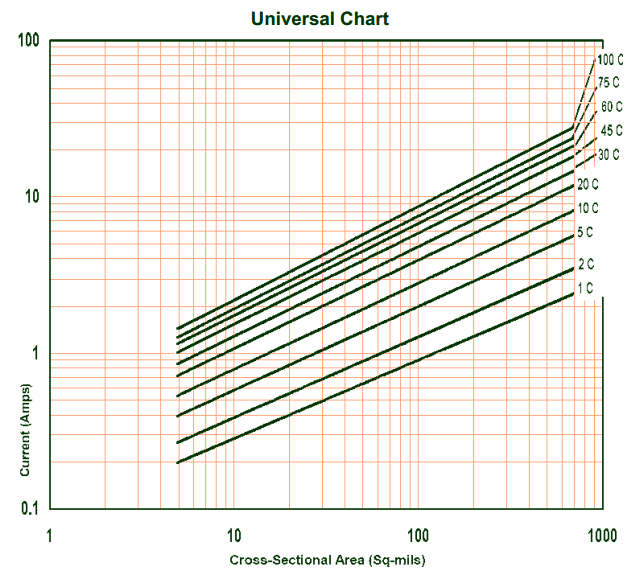
Firstly, use the Universal Chart to calculate an unadjusted cross-sectional area.
-
Then, a bunch of coefficients (modifiers) are found based on a number of other parameters. The parameters include:
- Thermal conductivity of the PCB
- The PCB thickness
- The proximity of the current-carrying track to a copper plane
- The thickness of the current-carrying track
-
Once all the coefficients are found, they are multiplied with the unadjusted cross-sectional area to give an adjusted cross-sectional area.
-
The adjusted cross-sectional area.
You can do this by hand, but it quickly becomes tiresome. Luckily, there is a calculator below which can do it for us!
IPC-2152 Track Current Calculator
The calculator uses equations built from the data provided in the IPC-2152 graphs. Data points were extracted from the graphs using WebPlotDigitizer (a great program by-the-way). Suitable trend lines were then fitted. In the case of the three-variable graphs, trend lines were fitted to the coefficients of the first set of trend lines.
The accuracy of the calculator (w.r.t. the IPC-2152 graphs) is quite high within the range of data provided by these graphs. Outside of that, extrapolation can become inaccurate quickly because some modifiers use 5th-order polynomials to model the data (this was the best choice). Other graphs were modelled with power equations of the form and are likely to be more accurate when extrapolated.
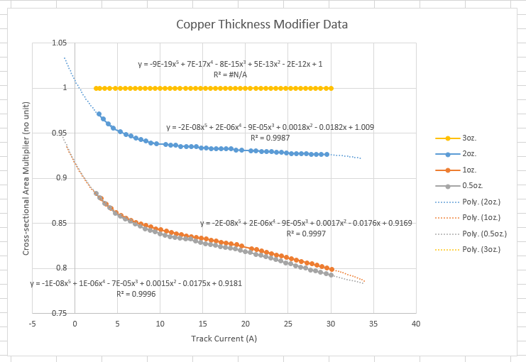
Below is an example of the trend-line fitting process. This image shows the “Copper Thickness Modifier” data from IPC-2152, along with 5th-order polynomials fitted to each data set. The data for the 3 oz. copper weight is a horizontal line at by definition.
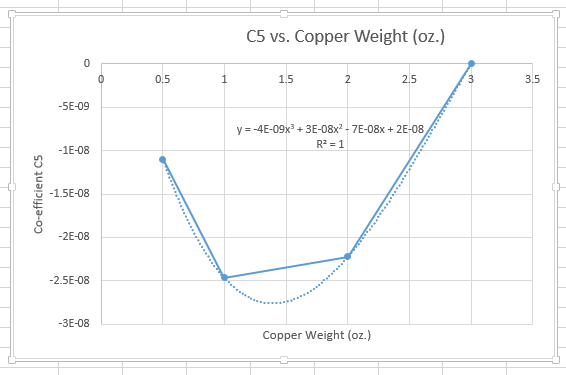
The coefficients of the above trend lines were then plotted against copper weight (a.k.a. track thickness). The graph below shows coefficient (the coefficient in front of ) against copper weight. These had their own trend lines fitted. Note that there are only four data points and the fitted trend line is a third-degree polynomial, which is guaranteed to fit the data perfectly. This is probably the most dangerous part of the “discrete graphed data sets to continuous equations” conversion.
The current is assumed to be constant (DC). However, you can use the RMS value for a pulsed current as long as the pulses are fast enough.
The temperature of the PCB material should NEVER exceed the relative thermal index (RTI) of the material. This is defined in UL746B as the temperature at which 50% of the material’s properties are retained after 100,000 hours.
Remember this calculator does not take into account other nearby heat sources.
IPC-2152 is designed to supersede the older IPC-2221A standard. It produces a more accurate track-width calculation, but requires more variables. If you don’t have all of those inputs (board thickness, plane proximity, substrate thermal conductivity), fall back to the IPC-2221A calculator below.
External Resources
Jack Olsen - How To 2152 (pdf)
Jack Olsen - How To 2152 (Excel based calculator)
Footnotes
-
Jack Olson. Determining Circuit Board Current Carrying Capability [pdf]. Retrieved 2026-05-28, from https://frontdoor.biz/PCBportal/HowTo2152.pdf. ↩