D-Subminiature (D-Sub) Connectors

D-Subminiature connectors (abbreviated to D-Sub connectors) were designed by ITT Canon in 1952. Large by today’s standards, at the time, these connectors where one of the smallest connectors available for a computer, hence the name “subminiature”. They are characterised by two or more rows of connections inside a “D” shape metal shell.
Older serial communication protocols such as RS-232 and RS-485 are commonly transmitted across D-Sub connectors. The DE-15 connector is commonly used for VGA connections between computers and screens.
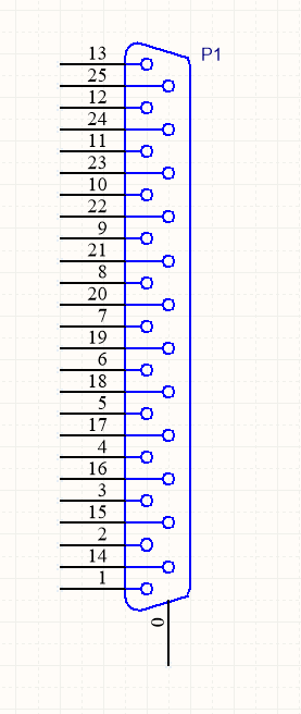
Schematic Symbol
I recommend using the unique schematic symbol style below for the range of D-sub-miniature connectors. It immediately identifies the connector to the viewer.
Sizes
The available sizes are shown in the table below.
Normal Density | High Density | Double Density | |||
|---|---|---|---|---|---|
Name | Num. Pins (layout) | Name | Num. Pins (layout) | Name | Num. Pins (layout) |
DE-09 | 9 (8-7) | DE-15 | 15 (5-5-5) | DE-19 | 19 (6-7-6) |
DA-15 | 15 | DA-26 | 26 (9-9-8) | DA-31 | 31 (10-10-11) |
DB-25 | 25 | DB-44 | 44 (15-15-14) | DB-52 | 52 (17-18-17) |
DC-37 | 37 (19-18) | DC-62 | 62 (21-21-20) | DC-79 | 79 (26-27-26) |
DD-50 | 50 (17-16-17) | DD-78 | 78 (20-19-20-19) | DD-100 | 100 (26-25-24-25) |
DF-104 | 104 (21-21-21-21-20) | ||||
Backshells
D-subminiature connectors which are attached to cables (i.e. are not PCB mounted or panel mounted) are designed to be fitted with a backshell. The backshell protects/encloses the wire connections from from the cable, as well providing mechanical support and strain relief for the cable.
Termination Styles
PCB Mount: The connectors has protruding pins (in either straight or right-angle orientation) so that the connector can be soldered to a PCB.
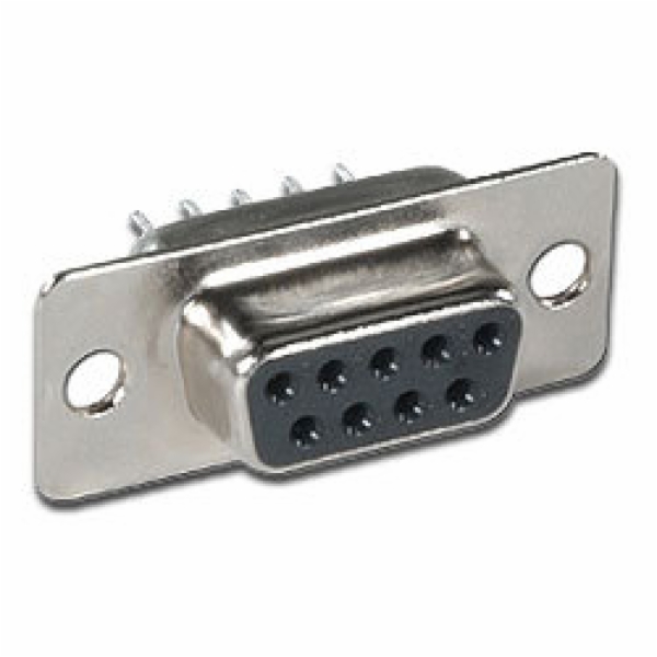
Solder Lug: Designed so that wires can be soldered onto the pins. This style of connector is designed to be panel mounted (not PCB mounted). Also called solder bucket.
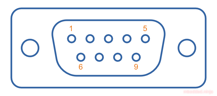
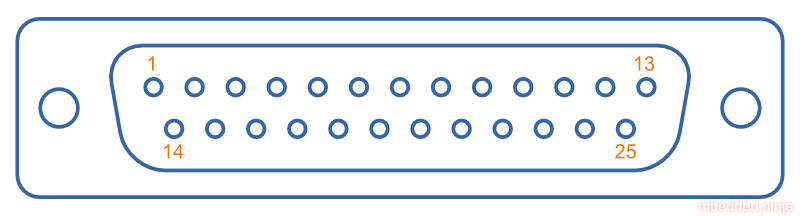
Pin Numbering
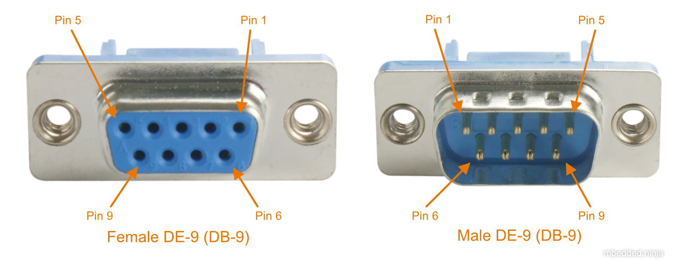
Uses
Many older consumer products and prototype circuits of all ages use the DE-9 connector for RS-232 communications. However, it is becoming less common, with USB-to-UART cables becoming more popular, which get connected directly to a microcontrollers pins through flying leads, standard header, or USB connector (in this case the USB-to-UART converter is usually on the board itself, i.e. Arduino boards).
Filtered D-sub Connectors
Filtered D-sub connectors have purposeful capacitance-to-ground (or more complicated filters) built into each one of the connectors pins.
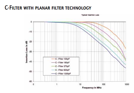
Compared to implementing the filtering on say, the PCB, filtering at the connector offers the advantage of increased EMI protection due to the filtering occurring at the point that the signal enters the enclosure (so the wires to the PCB don’t radiate noise). It also saves PCB space and simplifies PCB routing/layout.
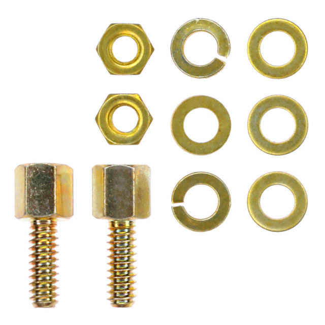
Screw Kits
You can buy pre-made screw kits, such as the TE Connectivity 5205817-1, which comes with all the necessary screws and associated hardware to secure two D-sub connectors together (I might point out here that screws are not required to make a connection, but help to make it more secure).
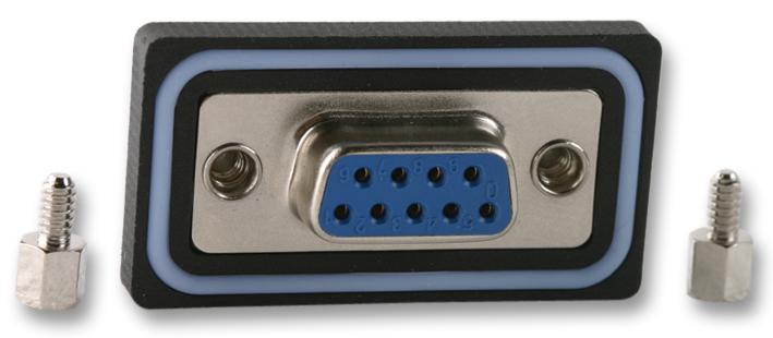
Waterproof Variants
Waterproof variants of D-sub connectors exist, the two most common being a DE-9 or a DB-25.