Antennas

Antennas are an electronic device which converts between electrical energy and electromagnetic waves. They are commonly used for transmitting and receiving radio frequency (RF) signals and can be used for communication and measurement applications.
Gain
The gain of an antenna is a measure of an antenna’s radiation efficiency (how well it converts electrical power into radio waves) and directivity (how focused the radiation intensity is in a particular direction).
Gain is defined as: The ratio of radiation intensity in a given direction to the radiation intensity that would be produced by an isotropic radiator (a theoretical antenna that radiates equally in all directions) with the same input power. As an equation:
Where:
- is the gain (unitless)
- is the radiation intensity of the antenna in a given direction (W/sr)
- is the radiation intensity of an isotropic radiator with the same input power (W/sr)
Key points to note:
- The definition states “with the same input power”. This means it takes into account the radiation efficiency of the antenna — the divisor is an isotropic radiator that took all of the input electrical power and converted it into radiation.
- Gain is specified in a given direction. If no direction is specified, it is usually assumed to be the maximum gain (the gain in the direction of maximum radiation intensity).
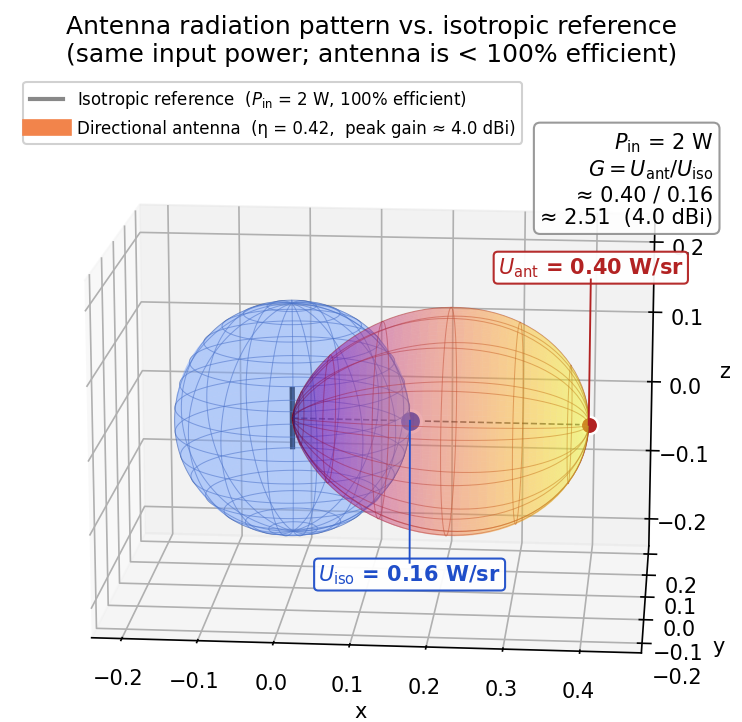
The image below illustrates how the gain of an antenna is calculated. Let’s assume we have an antenna with a single main lobe that points to the right and an input power of . The radiation pattern is shown by the multi-coloured (orange/yellow) surface. Also drawn is a reference isotropic antenna with the same input power (electrical power going into the antenna) and 100% efficiency, shown as the blue sphere.
The radiation intensity of the isotropic reference is the same in every direction and equal to the input power spread evenly over the full steradians of the sphere:
The directional antenna concentrates radiation into a main lobe. In this example, the peak intensity in the direction of maximum gain works out to (which already accounts for the antenna’s efficiency ). This value would usually be measured in a specialized laboratory setting. The gain is then:
Converting to :
Gain can also be defined as the product of the antenna’s directivity and its radiation efficiency:
Where:
- is the directivity (unitless)
- is the radiation efficiency (unitless, between 0 and 1)
Power Unit Converter
Use the converter below to switch between common RF power units. Edit any field and the rest update automatically.
Dipoles and Monopoles
Dipoles
Dipole antennas consist of two conductive elements that are typically of equal length and are fed at the center.
Monopoles
Monopoles only contain one conductive element, and use a ground plane to act as the “other half” of the antenna (all antennas need two conductive elements to radiate). A monopole has another image in the ground plane, which makes it electrically equivalent to a dipole. This is why a quarter-wave monopole is often used as an antenna design, since it can achieve similar performance to a half-wave dipole while being physically smaller.
Monopoles are naturally unbalanced and can be fed directly from a coaxial feed line. This is normally a benefit over dipoles, which require a balun to feed them from an unbalanced coaxial feed line. They are usually smaller than a dipole of the same frequency, since they only require one conductive element.
Impedance Matching
Some forms of antenna such as chip and PCB antennas sometimes require impedance matching to achieve good performance. Impedance matching is the process of designing the feed line and matching network to make sure the feed line matches the impedance of the antenna. Impedance mismatches can lead to reflections of the signal back towards the source, which can cause a reduction in the power delivered to the antenna and a decrease in the antenna’s performance.
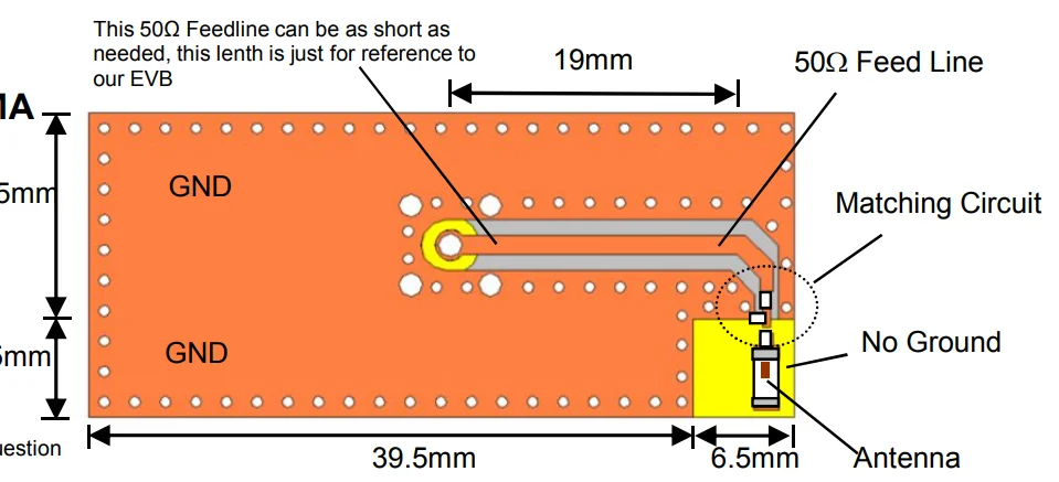
PCB Trace Antennas
PCB trace antennas are antennas that are made directly from copper traces on a printed circuit board (PCB). They are very low cost (i.e. no extra BOM cost beyond the PCB itself) and can be made relatively small (but not as small as chip antennas).
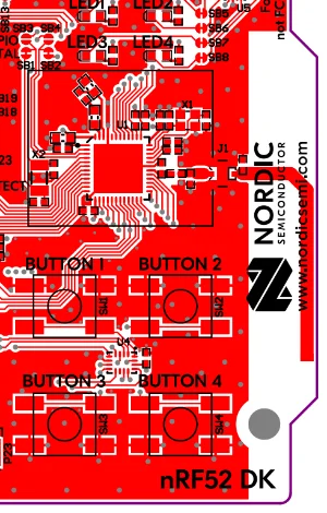
You have to consider the placement of other components surrounding the PCB trace antenna. The following diagram shows the minimum recommended clearances between a PCB trace antenna and other components.
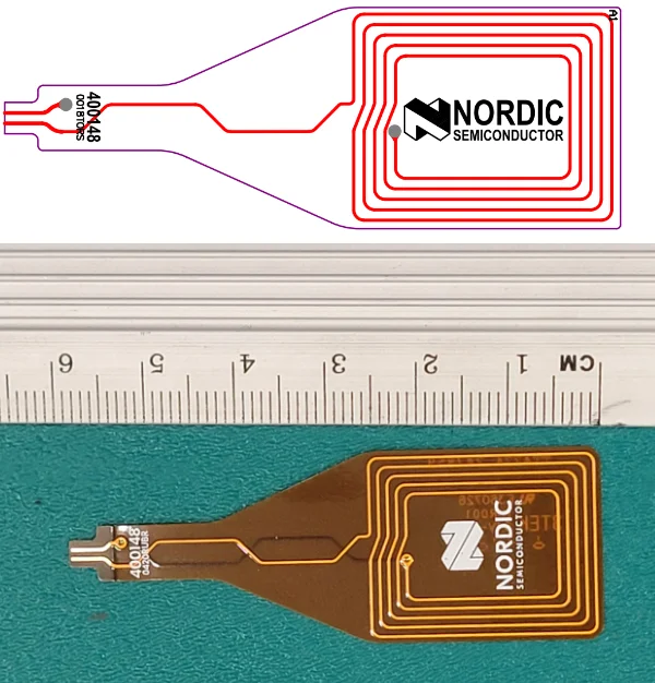
PCB trace antennas don’t have to be made of rigid materials, they can also be made in flex PCB form. Below is the Nordic Semiconductor RFID antenna that is provided with many of their development kits.
Dome/Puck Antennas
Dome (a.k.a puck) antennas are a type of enclosed antenna designed for use outside or rugged use.
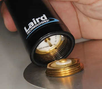
Many of the dome style antennas utilise the NMO mount shown below. NMO stands for “New Motorola Mount” and was a standard mount developed by Motorola for their land mobile radio antennas. It is still popular for robust external antenna connections, especially for vehicles.3
Many of the antennas designed for cellular communication support a range of frequency bands. For example, the Laird Connectivity TRA6927M3PW-001 4G/3G antenna simultaneously supports the 698-960MHz and 1700-2700MHz bands.4
Examples
Taoglas Olympian II 5G/4G (G45.A.201111)
The Taoglas Olympian II 5G/4G is a low profile, permanent mount dome style antenna that covers worldwide 5G/4G bands and is backwards compatible with 3/2G. It is 48.5mm tall and 50mm in diameter.5
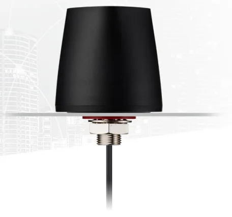
Interestingly, Taoglas recommends a “minimum of 1m cable length for stable antenna performance”. It works best when the antenna is mounted on a metal ground plane. The cable is 2m of RG-174 with a male SMA connector mounted on the end.5
Whip Antennas
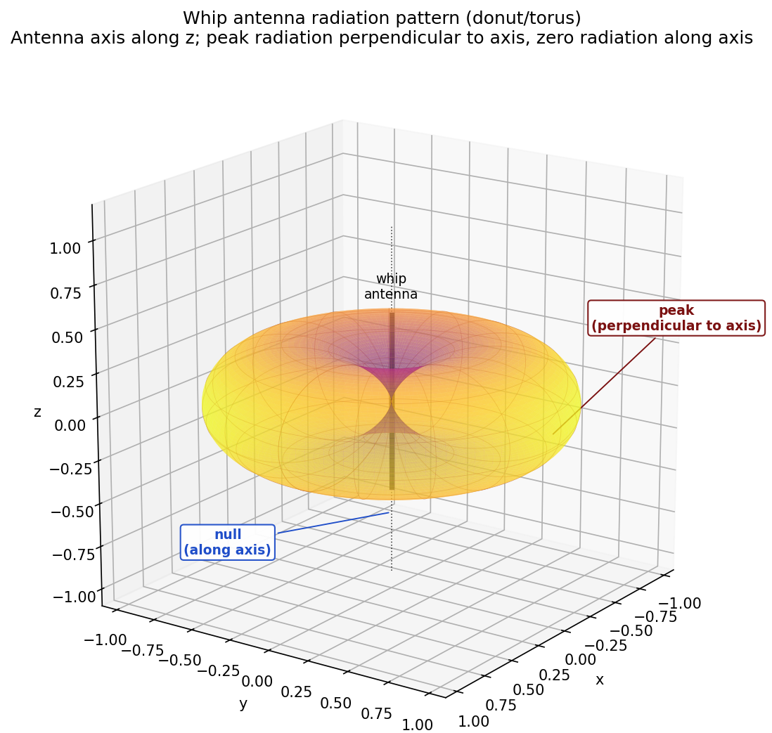
Whip antennas are made from a piece of straight, flexible wire. They are a form of monopole antenna. Their length varies from electrically short antennas of 1/10 wavelength to 5/8 wavelength. The most common is the quarter-wave whip which is 1/4 wavelength long. Their name comes from the fact they often flex and “whip” when disturbed.
Whip antennas radiate equally in all directions perpendicular to the axis of the antenna. The radiation power falls to zero on the antenna’s axis.
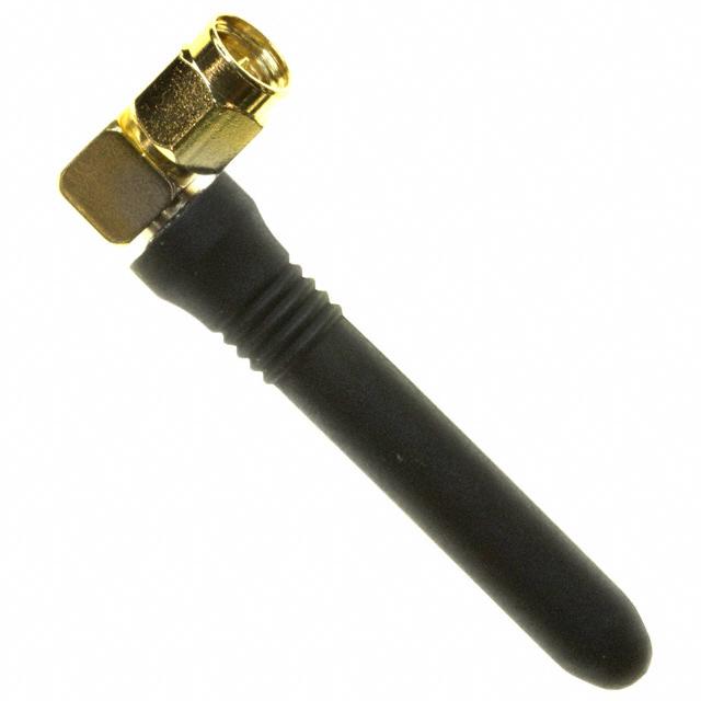
Rubber Ducky Antennas
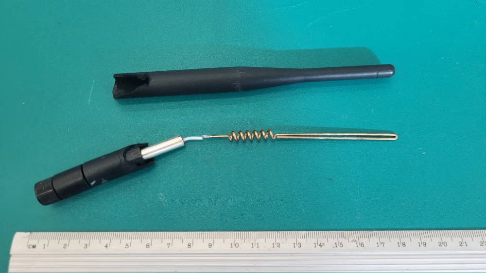
Rubber ducky antennas are a compact monopole antenna that are physically shorter than a quarter wavelength and feature a helical coil. Because they are shorter than a quarter wavelength, they require inductance to make them resonate at the desired frequency. Rather than base loading them with a discrete inductor (a.k.a. a base loaded whip antenna), a rubber ducky incorporates a helical coil into the antenna itself to provide the necessary inductance. This reduces the need for a separate inductor, and gives better performance since the inductance is distributed along the antenna’s length.6
Ever wondered what a rubber ducky antenna looks like on the inside? Below is an image of a rubber ducky antenna which has been sacrificed in the pursuit of knowledge. You can see the feed wire which leads up to the inductive coil and then the rest of the antenna. Interestingly the long straight piece is bent back on itself. I forgot to check if the copper was insulated or not. If not insulated, that would make the bending back especially intriguing.
Internal Counterpoise
Some rubber ducky antennas have a built-in counterpoise to act as the “other half” of the antenna. This reduces their dependence on an external ground plane and makes their gain and radiation pattern more consistent across different mounting conditions.
One example is the TE Connectivity ANT-2.4-CW-RCT-SS antenna. It is designed for 2.4 GHz applications and has an internal counterpoise.7
Chip Antennas
Chip antennas are antennas that are packaged in the familiar SMD chip form factor (e.g. 0603, 0805, 1206). They are very small and are soldered directly onto a PCB. They are typically omnidirectional (well, close enough) and have low gain (usually around -2 to 3 dBi).
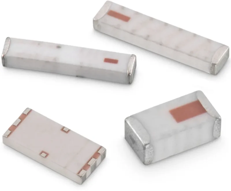
Most chip antennas are monopoles which require a ground plane with specific geometry to work correctly. It is important to follow the recommended copper plane and keep-out areas specified in the datasheet to ensure proper antenna performance, as chip antennas can be very sensitive to small changes.
Low temperature co-fired ceramic (LTCC) technology can be used to create chip antennas with multiple layers of circuitry.10
Some chip antennas are Planar Inverted-F Antennas (PIFAs).
Johanson Technology offer chip antennas from 433 MHz in 9820 size up to 20 GHz in EIA 0402 size.10 They state that it is not economical to make chip antennas for frequencies below 433 MHz due to the large size required.
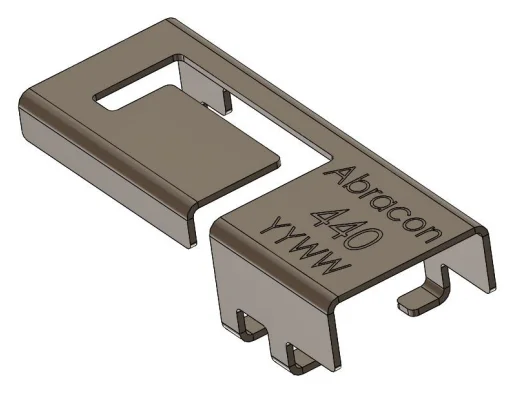
Stamped Metal Antennas
Stamped metal antennas are made by stamping a sheet of metal into the desired shape. They are very cheap to produce and can be small (but not as small as chip antennas).
Shorting Antennas
Note that shorting out an antenna is not an effective way of stopping it from communicating. At RF, a direct short with a piece of wire is no longer a direct short, and can for example, appear inductive. This means the antenna can still work, and sometimes make it perform better. I have shorted out cellular modem antennas before with pliers and the signal strength increased!
The Friis Transmission Equation and Free-Space Path Loss (FSPL)
The Friis transmission equation calculates the received power based on the transmitted power , antenna gains, signal wavelength and distance:
where:
- is the received power in Watts
- is the transmitted power in Watts
- is the transmitted antenna gain (no unit)
- is the receiver antenna gain (no unit)
- is the wavelength of the signal in meters
- is the distance between transmitter and receiver in meters
Footnotes
-
Nordic Semiconductor. nRF52 DK Hardware Files. Retrieved 2026-05-11, from https://www.nordicsemi.com/Products/Development-hardware/nRF52-DK/Download. ↩
-
Antenova. Resources - Literature [website]. Retrieved 2026-07-13, from http://www.antenova-m2m.com/resources/literature. ↩
-
Digikey TechForum (2017, Oct). NMO Connectors / Mounting [forum post]. Retrieved 2025-04-09, from https://forum.digikey.com/t/nmo-connectors-mounting/593/1. ↩ ↩2
-
Laird Connectivity. TRA6927M3PW-001 - 4G/3G Multiband Phantom Antenna [datasheet]. Retrieved 2025-04-09, from https://connectivity-staging.s3.us-east-2.amazonaws.com/2019-06/ANT-DS-TRA6927M3%200619_0.pdf. ↩
-
Taoglas. Olympian II 5G/4G (G45.A.201111) [datasheet]. Retrieved 2025-04-09, from https://www.farnell.com/datasheets/3676759.pdf. ↩ ↩2 ↩3
-
Wikipedia. Rubber ducky antenna [wiki]. Retrieved 2026-05-09, from https://en.wikipedia.org/wiki/Rubber_ducky_antenna. ↩
-
TE Connectivity. ANT-2.4-CW-RCT-SS [product page]. Retrieved 2026-05-09, from https://www.te.com/en/product-L9000032-01.html. ↩
-
Wurth Elektronik. 74889302450 Internal SMT Antenna [product page]. RS Components. Retrieved 2026-05-11, from https://nz.rs-online.com/web/p/smt-antennas/2389593. ↩
-
Johanson Technology (2017, Dec 22). Mini 2.45 GHz Antenna, AEC-Q200 Qualified (P/N 2450AT18A100E-AEC) [datasheet]. Retrieved 2026-05-11, from https://www.johansontechnology.com/docs/1129/2450AT18A100E-AEC_tCZ7Fpd.pdf. ↩
-
Johanson Technology. Understanding Chip Antennas Handbook — High Frequency Ceramic Solution [handbook]. Retrieved 2026-05-10, from https://www.johansontechnology.com/docs/4565/johanson-antenna-handbook.pdf. ↩ ↩2
-
Abracon (2022, Nov 1). PRO-OB-440 OnBoard 2.4 GHz SMD Antenna [datasheet]. Retrieved 2026-05-11, from https://abracon.com/datasheets/PRO-OB-440.pdf. ↩