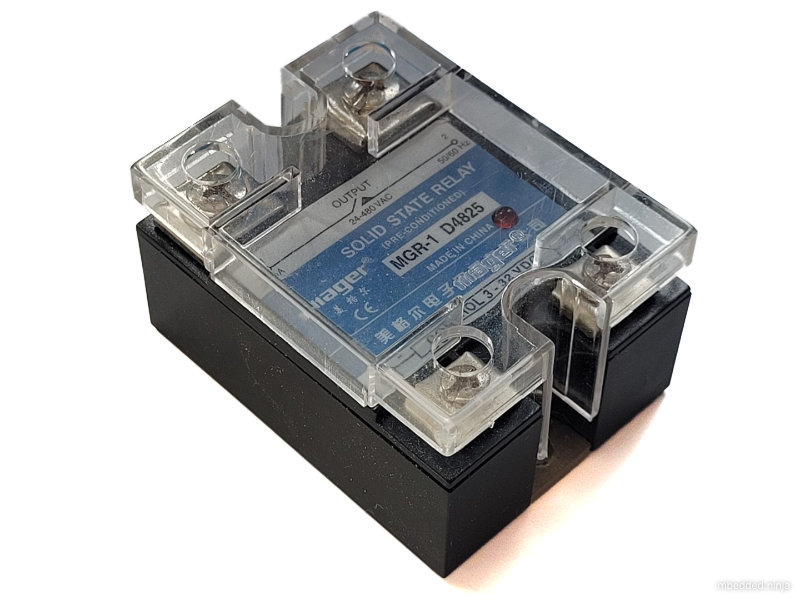
Solid State Relays (SSRs)

Solid-state relays (SRRs) are relays that use don’t have any moving mechanical parts involved in the switching. They use semi-conductor devices (normally MOSFETs) to perform the switching instead. The key feature that distinguishes SSRs from standard transistors is that they provide electrical isolation between the input and output. This is typically achieved by using an opto-coupler to drive the MOSFETs.
SSRs or more reliable than mechanical relays as there are no moving parts to wear out. They also have a faster switching times than mechanical relays. However, they are more typically more expensive for comparable voltage/current ratings and can be more easily damaged by over-voltage conditions.
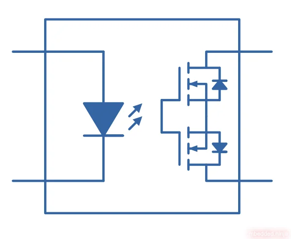
The normal way of doing this is to perform the switching with back-to-back N-channel MOSFETs whose gates are activated by a isolating opto-coupler (LED and receiver).
Below is the typical schematic symbol for a solid-state relay. It shows the inputs feeding the opto-coupler and the back-to-back MOSFETs that do the switching on the output:
Zero Crossings
You can purchase SSRs which are designed to switch on/off on a mains zero crossing. For example, the Sensata SPF240D25 is designed to turn on at the first zero crossing after the control signal is applied, and to turn off at the first zero crossing after the control signal is removed.2 This is suitable for resistive loads.
This is a placeholder for the reference: fig-sensata-spf240d25-internal-wiring-diagram shows the internal wiring diagram. Just like normal SSRs, it uses an opto-coupler (LED and phototransistor) to communicate the control signal to the switching circuitry across the isolation barrier. However, rather the the light directly going to the gates of back-to-back MOSFETs, it goes to control circuitry which implements the zero crossing detection and then controls the SCRs.
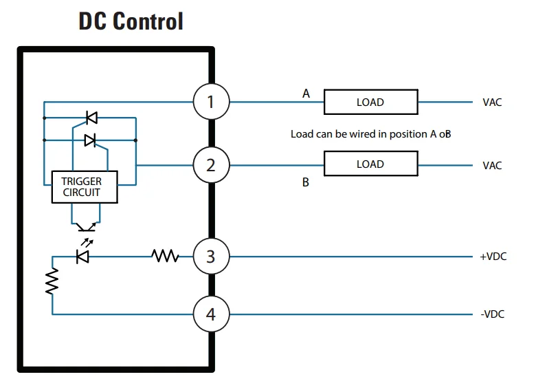
They also produce a variant which turns on immediately, and turns off at a zero crossing. This is more suitable for inductive loads.
Footnotes
-
Panasonic. PhotoMOS - GU SOP 1 Form A - High Capacity - Product Catalog [product catalog]. Retrieved 2024-09-11, from https://www3.panasonic.biz/ac/cdn/e/control/relay/photomos/catalog/semi_eng_gu1a_aqy21_gs.pdf. ↩
-
Sensata. SPF SERIES - PCB MOUNT SOLID STATE RELAYS [datasheet]. Retrieved 2025-07-10, from https://www.sensata.com/sites/default/files/a/sensata-spf-series-pcb-mount-ssr-datasheet.pdf. ↩ ↩2