BLDC Motor Control

The page is dedicated to how to control a brushless DC (BLDC) motor in an embedded system. This includes control methods for both trapezoidal and sinusoidal wound BLDC motors. There are many different ways to control a BLDC motor, from simple hall-effect based switching, to complex encoder based field-orientated control with space-vector modulation (if you have no idea what these mean, don’t worry, read on).
Acronyms And Terminology
| Subscript | Parameter | Units (metric) | Units (imperial) |
|---|---|---|---|
| Continuous Torque | Nm | oz-in | |
| Peak Torque | Nm | oz-in | |
| Continuous Stall Torque | Nm | oz-in | |
| Friction Torque | Nm | oz-in | |
| Continuous Current | A | A | |
| Peak Current | A | A | |
| No-Load Speed | rad/s | rpm | |
| Rated Power | W | W | |
| Terminal Voltage | V | V | |
| Input Power | W | W | |
| Output Power | W | W | |
| Torque Constant | Nm/A | oz-in/A | |
| Back EMF Constant | V/rad/s | V/krpm | |
| Motor Constant | Nm/sqrt(W) | oz-in/sqrt(W) | |
| Rotational Inertia | gram-cm^2 | oz-in-s^2 |
Motors
Important Parameters:
- Torque Constant: An important parameter which relates the torque to the DC current draw. All other things being equal, higher-quality motors will have a higher torque constant.
- Rated Speed: Most are rated in the range of 3000-6000rpm. The motor can be driven at slightly higher speeds than those rated by a technique that is called ‘flux weakening’
- Rated Current
- Cogging torque - This is the maximum torque the motor has when it is not being driven. This causes the rotation of the axle to feel ‘bumpy’ if rotated by hand when it’s not being driven. For smooth operation at low speeds (< 100rpm), the cogging torque has to be small (or nothing at all). You shouldn’t be able to feel this ‘bumpy’ phenomenon on motors with small cogging torques.
- Mechanical Time Constant: The time for the motor to spin up to full speed at rated voltage. Normally between 4-10ms. High performance motors can have a time constant as low as 1ms to speed up to 30,000rpm!
- Electrical Time Constant
- Winding Inductance: High precision motors typically have lower inductance. The winding inductance has the useful property of limiting the rate of change of current through the motor, and is what allows you to use PWM to produce smooth current. The lower the inductance, the higher the PWM needed to achieve the same current ripple.
- Number of pole pairs. The number of pole pairs is equal to the number of electrical revolutions per mechanical revolution. Typical BLDC motors have a number of pole pairs varying from 1 to 5. If the motors datasheet instead states the number of poles, this is just 2x num. pole pairs. Note that if the motor has more than 1 pole pair, you cannot orientate the motor to a known mechanical position without some type of feedback (hall-effect, encoder).
The 3 phases of a BLDC motor are usually labelled either A, B, C or U, V and W.
Cogging torque is due to the variation in airgap permanence or reluctance of the stator teeth and slots above the magnets as the motor rotates.
Ripple torque is the torque produced by the interaction between the stator and rotor MMF. Ripple torque is mainly due to fluctuations in the field distribution.
The motor windings can be wound to either give trapezoidal or sinusoidal feedback, which relates to the control methods mentioned further down on this page. As quoted by Shiyoung Lee, Ph.D., A COMPARISON STUDY OF THE COMMUTATION METHODS FOR THE THREE-PHASE PERMANENT MAGNET BRUSHLESS DC MOTOR),
The simulation results verify that mismatch of the back-EMF waveform and commutation method produces ripple rich torque. Therefore, the BLDC motor and trapezoidal(six-step) commutation and the PMSM and sinusoidal commutation are the most desirable combination to produce minimum torque ripple.
So it pays to get the right motor for the right job!
Trapezoidal vs. Sinusoidal
There are two standard ways of winding the coils. One is to produce a trapezoidal shaped BEMF, the other produces a sinusoidal shaped BEMF. Sinusoidal motors have lower torque ripple (less vibration, mechanical stress etc. etc.), but suffers from higher switching losses and greater drive complexity than a trapezoidal motor. For this reason trapezoidal motors are very common.
In a sinusoidal motor, current travels through all three windings at any point, while in a trapezoidal motor, current only flows through 2 of the 3 windings. Sinusoidal motors come under a number of names, including PMSM (permanent magnet synchronous motor), an AC servo motor, or BLAC (brushless AC, a term used by Atmel). Trapezoidal designed motors go under the name BLDC (brushless DC).
Positional Sensing
Because there are no brushes to switch the current in the windings (commutation), the position of the rotor relative to the stator needs to be known so that the current can be switched externally. There a three main methods for detecting where the rotor is:
- Hall-Effect Sensors
- An Encoder
- Zero-crossing (aka sensor-less)
Hall-Effect sensors output a voltage relative to the magnetic field strength (or more technically, the magnetic flux density). Three of them are spaced 120° apart from each other and designed so that their output voltage changes rapidly as the phase coils require switching. This can make the switching electronics easy to implement. Be careful, some hall-effect sensors can be open-drain, even though the motor’s datasheet suggest that the output is fully driven!
The encoder method uses, well, an encoder attached to the axle to determine rotor position. This is more complex than the hall-effect method as the encoder output requires decoding. The encoder is typically of the incremental quadrature type, which requires a counter to count the pulses and a phase detection logic to determine the direction. This feedback method can also suffer from glitches which causes the encoder count to drift from the correct value. The PSoC microcontroller has a very nice quadrature decoding component with built-in glitch filtering.
Zero-crossing has become popular in recent years due to the fact it requires no sensors, making it cheap to implement. It is the method of measuring the voltage of the floating winding during operation (1 winding is always undriven), to determine the position of the rotor. One disadvantage of this method is that it does not work below a minimum speed (because the voltage is too small).
Trapezoidal Control
A common example of a trapezoidal (or block) commutation cycle of a BLDC motor with hall-sensor feedback is shown in the below table. This will drive the motor in one particular direction. This can be used to form a LUT for quick hardware/software commutation.
| Commutation Table | |||||
|---|---|---|---|---|---|
| Sensor Output | Driver Input | ||||
| HS1 | HS2 | HS3 | A | B | C |
| 0 | 0 | 1 | X | HI | LO |
| 0 | 1 | 1 | HI | X | LO |
| 0 | 1 | 0 | HI | LO | X |
| 1 | 1 | 0 | X | LO | HI |
| 1 | 0 | 0 | LO | X | HI |
| 1 | 0 | 1 | LO | HI | X |
where HS1, HS2, and HS3 are the hall-effect sensors, and A, B, and C are the motor phases of a 3-phase star-connected BLDC motor. Note that either the high-side, low-side, or both driver inputs can be modulated with a PWM signal to provide speed control.
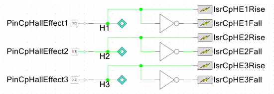
The schematic below shows the hardware used in a PSoC 5 microcontroller to perform hall-effect based trapezoidal commutation. With the correct mux selects, this control method can run completely from hardware and be completely processor independent (when running at a constant duty-cycle).

Sinusoidal Control
The benefits:
- Smoother operation/less torque ripple than trapezoidal
- Greater efficiency/less heat dissipation
- Able to run the motor at slower speeds
The disadvantages:
- Complex control
- Embedded firmware uses more flash/ROM space
- More processing power used
- Slightly lower maximum torque (although third-harmonic injection can reduce this)
- Hall-effect feedback becomes insufficient at low speed with varying loads, and optical encoders are preferred
- Back EMF feedback is not possible
Sinusoidal control (also known as voltage-over-frequency control) is more complex than trapezoidal techniques, but offers smoother operation and better control at slow speeds.
Look-up tables (LUTs) are recommended over using the sin() function due to speed issues. The sin() function in C is computationally intensive and can easily create delays that affect the performance of the control algorithm. The implementation of the sin() is platform dependent, but for example, using the GCC compiler on a PSoC 5 Cortex-M3 processor, calculating the sin() function three times (once for each phase), took approximately 24,000 clock cycles. With a processor running at 48MHz, this is about a 500us delay. Considering a 4-pole BLDC motor spinning at 6000rpm takes about 830us to move between commutation states. In each commutation cycle you want at least 6-bit resolution (64 PWM changes), and as you can see, the delay in calculating sin() is far too large.
With a LUT that stores floats, and a small amount of float multiplication (no divide) on an embedded processor that does not have floating point hardware support (such as the ARM Cortex-M3), you could expect the look-up and assign process to take around 500-1000 clock cycles (maybe 20us at 48MHz). This is a big reduction over using the sin() function!

Phase displacement. Sinusoidal control requires three PWM signals, preferably dual-output with adjustable dead-time for synchronous switching.
Example LUT Code
The following code is an example of how to create a LUT in the C programming language. This function calculates the LUT values at run-time, using the sin() function. In space constrained applications it may pay to pre-calculate the values and save them directly into flash. More help with the C language can be found here.
#include <math.h>
#define configBLDC_MAX_SINE_LUT_VALUE (1000)#define configNUM_SINE_LUT_ENTRIES (500)
float _sineWaveLut[configNUM_SINE_LUT_ENTRIES] = {0};
//! @brief Populates the sine LUT//! @details The sine LUT is placed in RAM for fast access.//! Call as part of the initialisation sequence.//! Shifts sinewave so that values never go negative,//! making it easy in ISR to multiply by scaling factor to get duty cycle//! @note Not thread-safe. Call from Bldc_MainTask() only.//! @privatevoid Bldc_FillSineLut(void) {    uint16_t i = 0;    // Populate LUT    for(i = 0; i < configNUM_SINE_LUT_ENTRIES; i++) {        double radians = (((double)i/(double)configNUM_SINE_LUT_ENTRIES)*360.0)*(configPI/180.0);        _sineWaveLut[i] = (configBLDC_MAX_SINE_LUT_VALUE/2.0)*sin(radians) + (configBLDC_MAX_SINE_LUT_VALUE/2.0);    }}
Third-Harmonic Injection
With a pure phase-neutral sinusoidal drive, the maximum phase-to-phase voltage is only roughly . This can be improved by ‘injecting’ the sine wave with the third harmonic. The first thing you may think is, won’t this disrupt my nice and smooth sine wave control? Well, no, because as it happens, the third harmonic is in-phase with every winding (which are 120° apart), and since it is applied to every winding, the phase-to-phase waveform does not change. It does however flatten the phase-neutral waveform, making the PWM become under-modulated. You can then scale this back up to full-modulation, and gives approximately a 16% phase-to-phase voltage increase.
To implement third-harmonic injection, all you have to do is add the third-harmonic to the sine-wave LUT. The third-harmonic has an amplitude that is 1/6 of that of the fundamental (your original sine wave). You’ll notice that the maximum value in the LUT has decreased. At this point, scale up all the values in the LUT so they use the full-range again.
Sensor Field Orientated Control (FOC)
The benefits:
- You can control motor parameters which relate directly to its physical behaviour (the variables make sense to a human)
- Angle can be determined from phase currents (usually using a sliding state estimator), no encoder needed
The disadvantages:
- Greater control complexity than trapezoidal or sinusoidal
- Requires fast processor to execute necessary maths
- Requires phase current to be measured (usually with low-side current sense resistors and an ADC)
- Requires the tuning of three PID loops (usually)
Sensor field orientated control (also called vector control) is a permanent magnet motor control method that allows one to regulate both the speed and torque independently from each other. However, this form of control is more computationally intensive than trapezoidal or sinusoidal. Part of the complexity is due to the need to be able to measure both the current going through the windings, while both trapezoidal and sinusoidal only requires positional feedback. Clarke (aka alpha-beta) and Park transforms (aka d-q) have to be calculated with the phase currents.
The Clarke Transformation (alpha-beta)
The Clarke transformation (also called the transformation, and occasionally called the Concordia transformation, but I don’t know why!) is the projection of three separate sinusoidal phase values onto a stationary 2D axis.
The unsimplified Clarke transformation equation is shown below:
where:
= current in motor winding A
= current in motor winding B
= current in motor winding C
= the Clarke transformed currents
We are fortunate that when using a star-connected BLDC motor (most are!), there is no neutral connection, so the three phase currents must sum to zero (). Using this constraint to eliminate , we can simplify the equation to:
If you want the code to do the Clarke Transformation (written in C++, and designed for embedded applications), check out the GitHub repository Cpp-ClarkTransformation.
The Park Transformation (dq)
Park transformation is a projection of three separate sinusoidal phase values onto a rotating 2D axis. The rotating axis (d, q) of the Park transformation rotates at the same speed as the rotor. When the projection occurs, the currents and remain constant (when the motor is at steady-state). It just so happens that controls the magnetizing flux, while controls the torque, and since both parameters are separate, we can control each individually!
The Park transformation equation is shown below:
where:
= current in motor winding A
= current in motor winding B
= current in motor winding C
= the Park transformed currents
If you want the code to do the Park Transformation (written in C++, and designed for embedded applications), check out the GitHub repository Cpp-ParkTransformation.
The Control Loop
The following picture shows the control architecture for a PMSM motor controlled with a PSoC microcontroller.
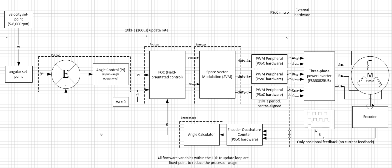
It is standard practice to set to some value depending on the torque/speed required, while keeping zero. This is because does nothing to help make the motor spin, and just wastes electrical energy as heat. However, there is a technique called flux weakening, and this is done by making negative. It will allow the motor to spin faster than its rated speed, in a zone called ‘constant power’. I have had good experiences at using this to squeeze more RPM out of BLDC motors that weren’t requiring much torque. A good method is to make proportional to (but always negative, no matter what sign is, which essentially gives you a fixed drive angle which is over 90°). You can use this equation to work out the proportion of that has to be for a certain angle.
where:
= ratio ()
= drive angle
FOC typically requires three PID loops, one medium-speed loop for controlling the velocity and two high-speed loops for controlling and .
There are two methods to measure the phase currents. The first involves just one current sense resistor on the DC return path from the motor, while the second requires three current-sense resistors, one on each leg of the three-phase bridge controlling the motor.
The dynamic equations for FOC linking voltages, currents and torques are:
During constant flux operation (which is normal operation, all the flux is created by the permanent magnets), becomes 0. This simplifies the torque equation into that similar to a brushed DC motor as:
Equations
The Lenz-Faraday model for field orientated control is:
where:
= statoric resistance
= statoric voltages
= statoric currents
= global fields
PWM Frequency
So what PWM frequency do I choose? The PWM frequency is a trade-off between torque ripple and switching losses. Most controllers use a frequency between 10-20kHz. If you want to reduce the audible noise from the motor, try using a frequency between 17-20kHz (outside the audible range of most adults).
Deadtime
Dead-time is only important if you are going to use synchronous rectification (i.e. switching on the MOSFET rather than letting the body diode conduct when current is flowing through it in the reverse direction). In this case, during the off-time of the PWM signal, the complementary (on the same leg of the bridge) MOSFET(s) to those that are being switched are turned on. This allows the reverse current that would be usually be flowing through the inherent body diodes to instead flow through the MOSFET, resulting in lower heat losses (MOSFETs have a lower on ‘resistance’ than diodes). Dead-time between turning on the leg MOSFETs off and the other on is needed to prevent shoot-through.
Note that if the duty-cycle of the PWM causes either the on or off-time to be less than the dead-time, it will appear as if the PWM stops working. This will happen at its two duty cycle extremes (at the top and bottom of the sine wave). Don’t be alarmed, this is normal and totally acceptable behaviour.
Open-Loop Feedback
Fully open-loop control (no hall-effect, encoder, or BEMF feedback) can be used in applications where torque ripple and efficiency are not important. The load has to be also relatively constant for this to work.
Closed-Loop Voltage Feedback
Closed-loop voltage control is when feedback is used to commutate the currents, and the PWM duty cycle is varied from 0-100% to control the speed of the motor (but with no velocity control). With this method, you have full control of the motors speed from 0-100%, but the motor’s speed may vary as the load changes. As the load is increased, the current will increase, and the rpm of the motor will drop. It is called ‘voltage’ control because you can set the PWM duty cycle, which determines the voltage across the windings.
Closed-Loop Velocity Feedback
Closed-loop velocity control involves controlling the rpm of the motor to a desired speed. The maximum currents must be taken into consideration when doing constant velocity control, as they may get very large if the motor stalls.
Feedback Can Come From:
- Hall-effect sensors (o.k.)
- Optical encoder (better, especially at slow speeds)
- Back E.M.F (good, but not at slow speeds)
Control Methods:
- PID PWM Control (soft or hard-chopping)
Closed-Loop Current Feedback
Closed-loop current control will give you a constant output torque. This means that the motor will slow down when the load is increased, and speed up when it is decreased.
Feedback Can Come From:
- Low-side current sense resistors and single-sided ADC
- High-side current sense resistors and a differential ADC
Control Methods:
- PID PWM Control
Sliding Mode Observer
Used to provide estimates on the position and speed of the rotor when not using encoder or hall-based feedback.
Controller Bandwidth
Controller bandwidth is an important term which is used to define the update rate or speed of a particular control section for a motor. It is usually referred to when talking about the “Current Controller Bandwidth”, a control loop that measures the phase currents of a brushless motor and updates the control variable accordingly (usually with a PID loop). This is commonly used with FOC control and SVM. Slow current controller bandwidths are around 300Hz, while faster bandwidths are in the 10-50kHz range (which updates the duty at the same speed as the PWM itself!). Higher current controller bandwidths are needed for lower torque ripple and slower motion (1-50rpm).
Code Execution Time
The execution time of the code which controls the PWM duty cycle is critical, especially when using sinusoidal or sensor field orientated control. Here are the best ways of making sure the code runs quickly
- Do not use the
sin()function, instead use a LUT - Do not use any division operators (instead, convert to a double, and multiply by the inverse, if inverse is already known or can be computed more quickly than a normal division) e.g.
number1*(1/number2) - Using fixed-point arithmetic rather than floats or doubles.
I have an open-source fixed-point library designed for running on embedded systems.
- Try to minimise function calls. Use the inline parameter if possible
- Pre-calculate any maths that can be done before-hand
- Make sure the compiler optimises for speed, not space
See the C Programming page for more help on this subject.
BLDC Maths
Some useful equations…
where = number of pole pairs, and there are 6 commutation steps per electrical cycle (six-step commutation).
Flux = Magnetic field lines per unit area
Related ICs
FSB50825US - Fairchild Smart Power Module (SPM)
- Package: SPM-23
- Shoot-through Protection: No
- Onboard Logic: None (microcontroller required)
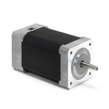
Standard Enclosures
The NEMA17 and NEMA23 are two common sizes that BLDC motors come in. This designation defines the mounting hole pattern for the motor.
The NEMA17 mounting hole dimensions are shown below. The dimensions are in millimeters.
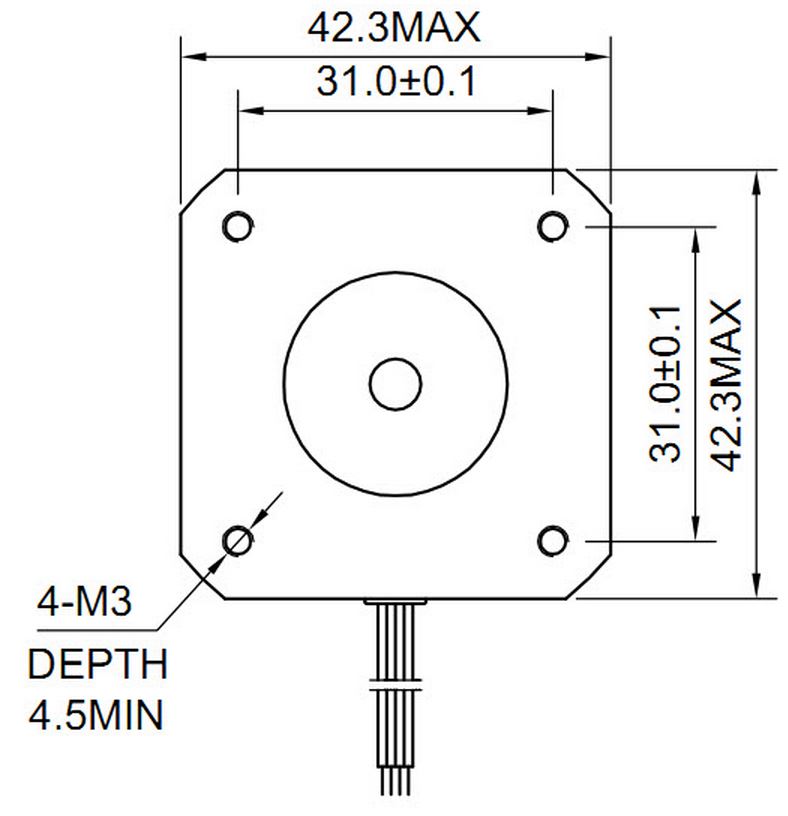
The NEMA23 mounting hole dimensions are shown below. The dimensions are in inches.

External Resources
One of the best documents that I’ve seen about BLDC motor theory is James Robert Mevey’s “Sensorless Field Orientated Control Of Brushless Permanent Magnet Synchronous Motors”. Click here to download a local version.
The second best is MicroChips AN885 - Brushless DC (BLDC) Motor Fundamentals.
And then once you’ve read those, check out AN857 - Brushless DC Motor Control Made Easy. This links the theory with a practical implementation of the hardware and firmware, supported with examples.
A competing document is NXP’s AN10661 - Brushless DC Motor Control Using The LPC2141. For the visual learners, this one has more colourful pictures than Microchip’s, but it has less depth.
RoboTeq (www.roboteq.com) have some very cool BLDC motor controllers. They are highly configurable, offer a huge number of features, and can drive very powerful motors (+100A).
If you’re a fan of animations (who isn’t, visual learning rocks!), then check out Nanotech’s Stepper/BLDC animations (http://en.nanotec.com/support/tutorials/stepper-motor-and-bldc-motors-animation/). A flash program which allows you visually watch the motors operation as you step through commutation cycles. Also lets you change the type of motor!
If you want to delve into the arena of Sensor Field Orientated control, the Atmel’s AVR32723 - Sensor Field Orientated Control For Brushless DC Motors with AT32UC3B0256 should be the first port of call. “Brushless Permanent Magnet Servomotors” is a good article explaining the differences between BLDC motors and PMSMs, as well as equations for FOC.