RC Charging Circuits

RC charging circuits are circuits which charge a capacitor through a resistor. They appear in almost all electronic designs in some form or another. They are used for things such as simple time delays, primitive oscillators, debouncing, and filtering.
This page looks at how the RC circuit responds in the time domain. If you are interested in its frequency response, see the Analogue Filters page.
The Circuit
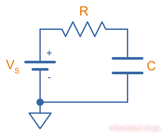
Assuming the capacitor’s voltage started at at , and a constant supply voltage is applied across the capacitor and resistor, then the capacitor’s voltage at any time is1:
where:
is the voltage across the capacitor, in Volts
is the supply voltage, in Volts
is Euler’s number,
is the time, in seconds
is the resistance, in Ohms
is the capacitance, in Farads
can be replaced with a concept called a time constant, where . This gives:
The capacitor voltage with respect to time is shown below.
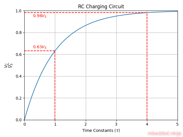
The capacitor’s voltage starts off at and charges towards . However the charging rate follows an exponential decay, the rate gets slower and slower. Mathematically, the capacitor’s voltage never reaches . However for most practical purposes you can consider the capacitor “fully-charged” after about 5 time constants.
What is the Time Constant?
The time constant is a way of simplifying the analysis of an RC circuit and lets you think and talk about the circuit in a consistent manner.
After 1 time constant (), then the equation simplifies to:
So you know that at , your capacitor has charged to 63% of the supply voltage. The beauty of is that you can quickly calculate it for any RC circuit and get a feel for how long it will take to charge (it is also very useful when looking at RC filters). The table below shows various time constants and the voltage level on the capacitor at that point.
| Time Constant | Voltage as Percentage of Supply |
|---|---|
| 1 | 63.2% |
| 2 | 86.5% |
| 3 | 95.0% |
| 4 | 98.2% |
| 5 | 99.3% |
Note that by 5 time constants, the voltage is at 99.3% of the supply voltage. This is generally considered to be the point at which it is “fully charged”.
Footnotes
-
Electronics Tutorials. RC Charging Circuit [website]. Retrieved 2024-02-16, from https://www.electronics-tutorials.ws/rc/rc_1.html. ↩