Columbus Radio

The Idea…
To bring an old, broken valve-based antique radio into the digital age with the ability to stream audio from the internet, a plugged-in USB stick, or a networked computer. All while keeping the classic retro radio look.
The Original Radio
My partner bought this lovely vintage, but worn valve-based radio at an auction many years ago for NZ$5. Bargain!
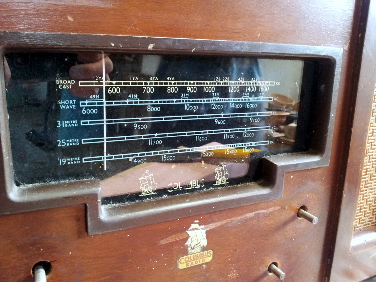
Even though it was worn and torn, you could tell it had been beautifully made and with attention to detail. Different veneers were expertly crafted into each wooden face of the cabinet. The rear showed you the inner-workings, large valves, plate capacitors and pulley systems!
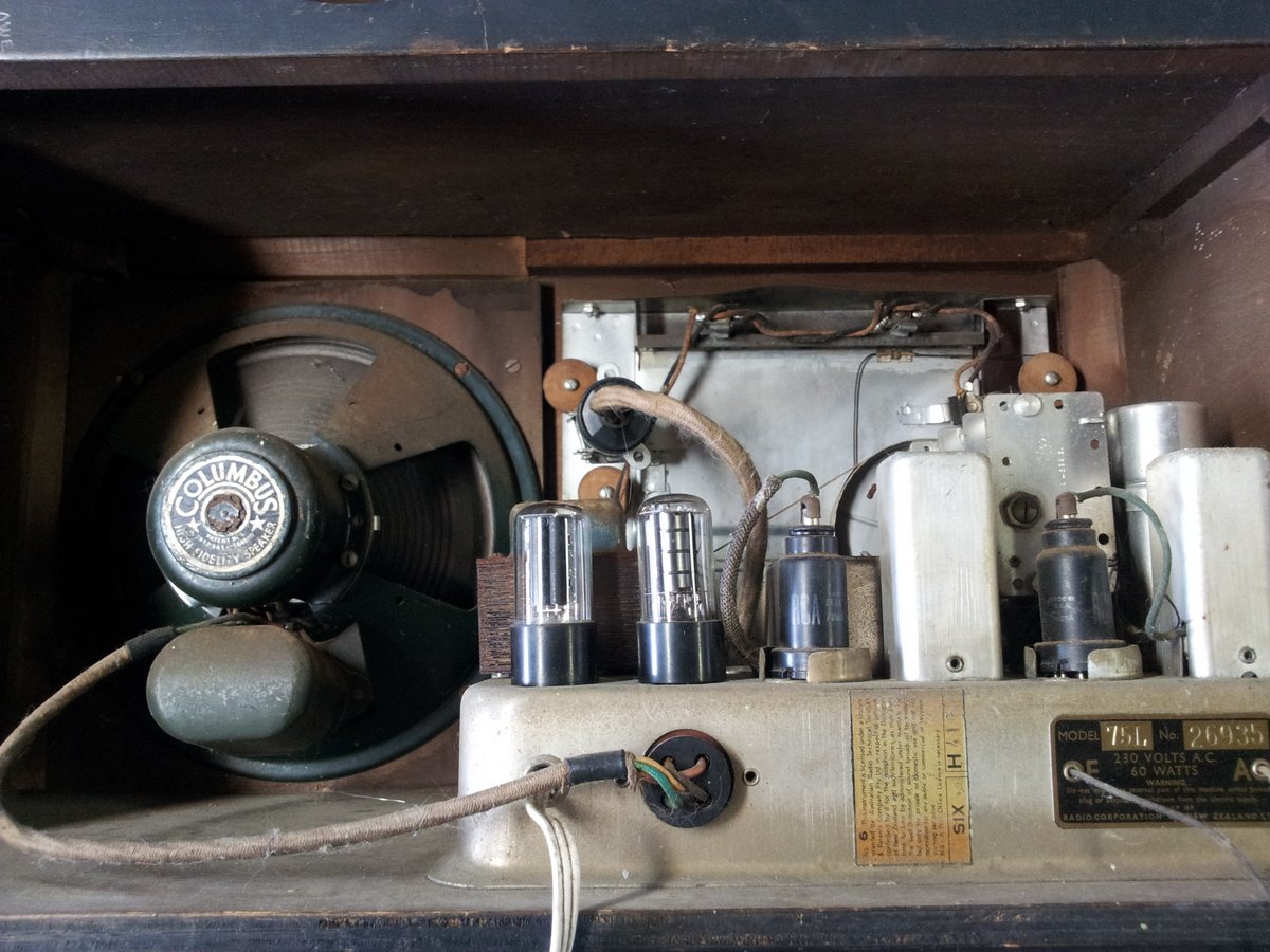
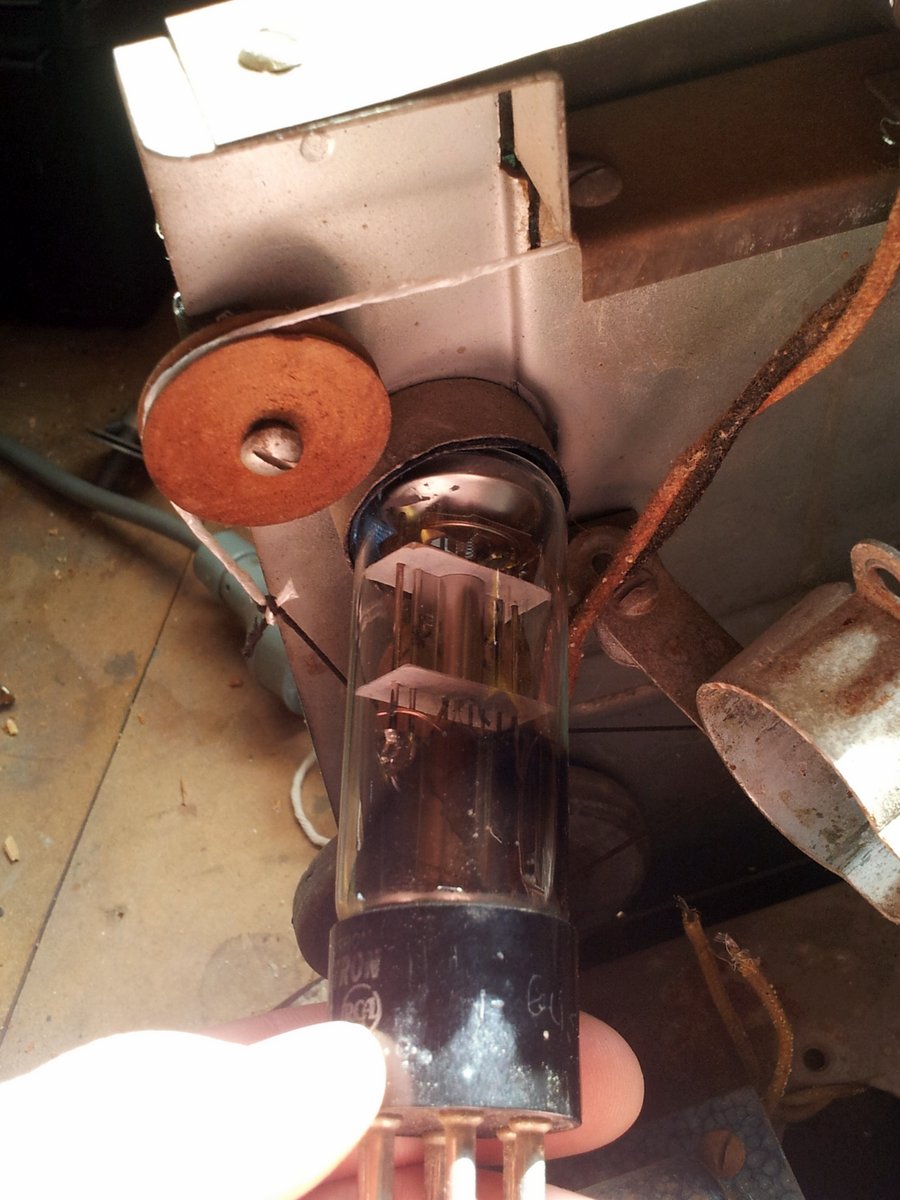
The original electronics!
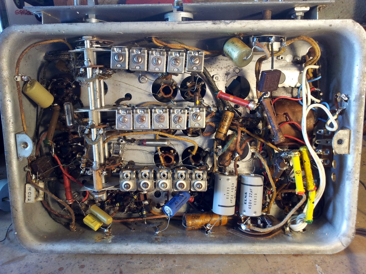
Woah! I had seen nothing like it before. I had heard of the style of board-less circuit design in where the components themselves supported one another, but only ever seen “new age” artistic examples of it (for instance a digital audio amplifier). And the component density was crazy! There were bare wires running past each other in free space with only mm’s of clearance. Tabs had been added to the metal enclosure at frequent intervals around the outside to serve both as a grounding point and a mechanical support.
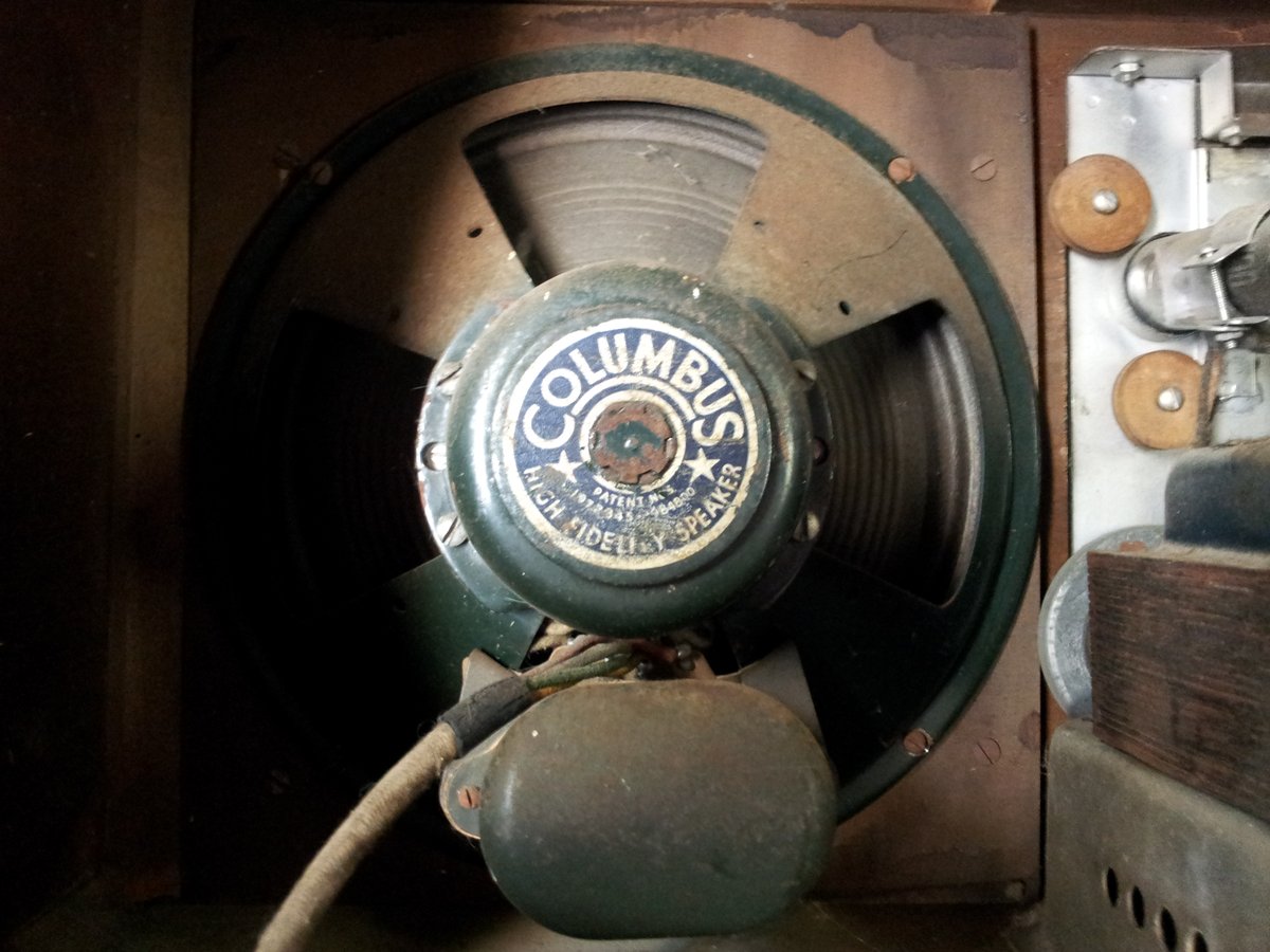
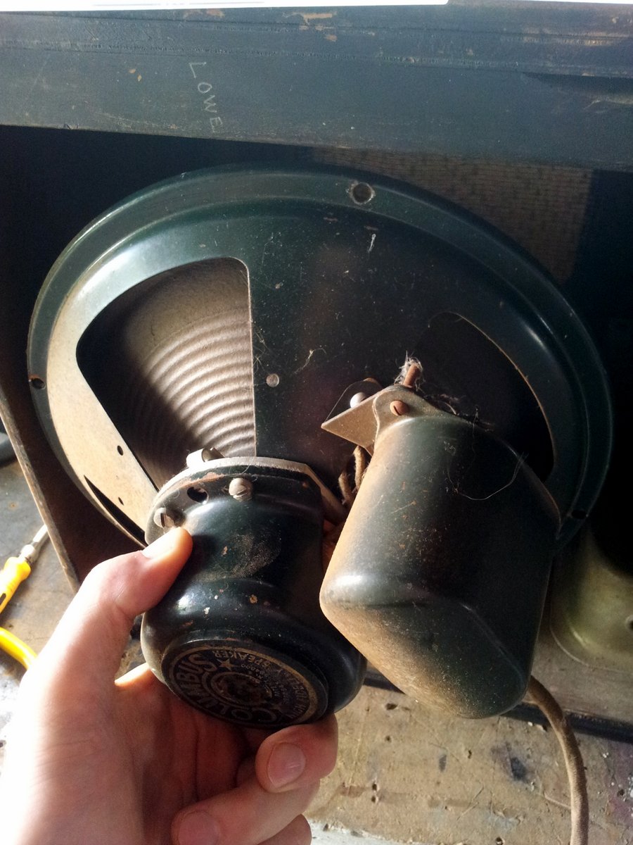
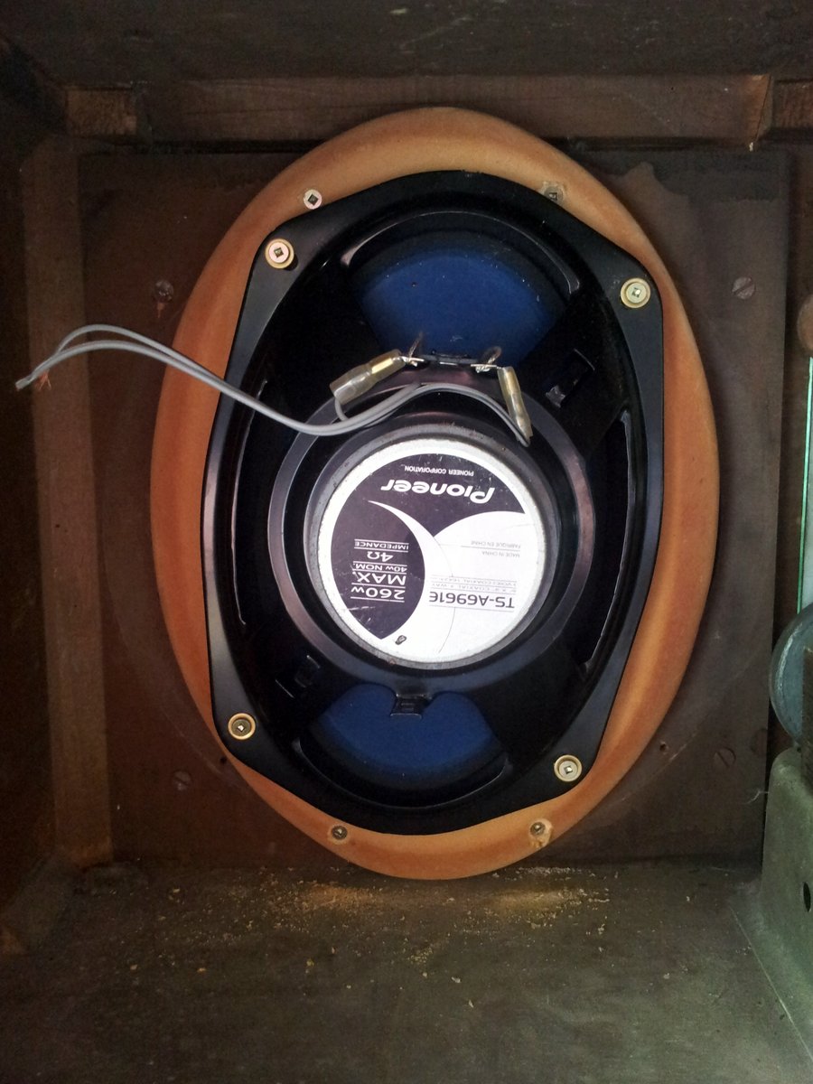
Oh and don’t forget the classic speaker…
UPDATE 2015-01-12: I found this webpage which describes the Columbus radio brand and its origins. Based on this information, the radio was made in New Zealand sometime between 1937 and 1961.
Mechanical
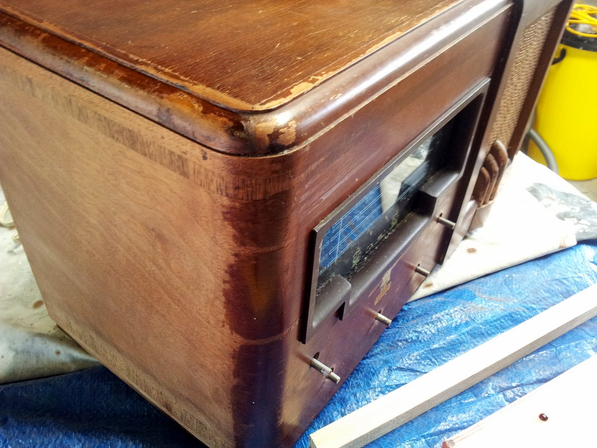
Stripping The Cabinet
The radio’s enclosure was in a pretty sad state when I first laid hands on it. The wood had a faded, mottled and cracked look to it. The knobs and their pulley systems (yes, it had pulley systems) had jammed. The glass panel with the screen printed radio bands on it had bits of text missing.
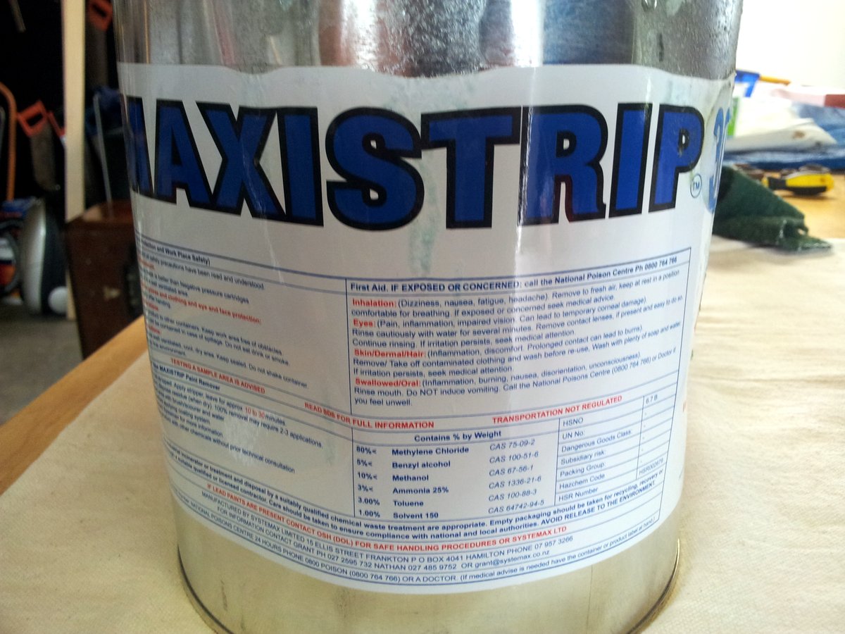
I tried a few different paint strippers (because my father had all of these lying around).
 |  |  |
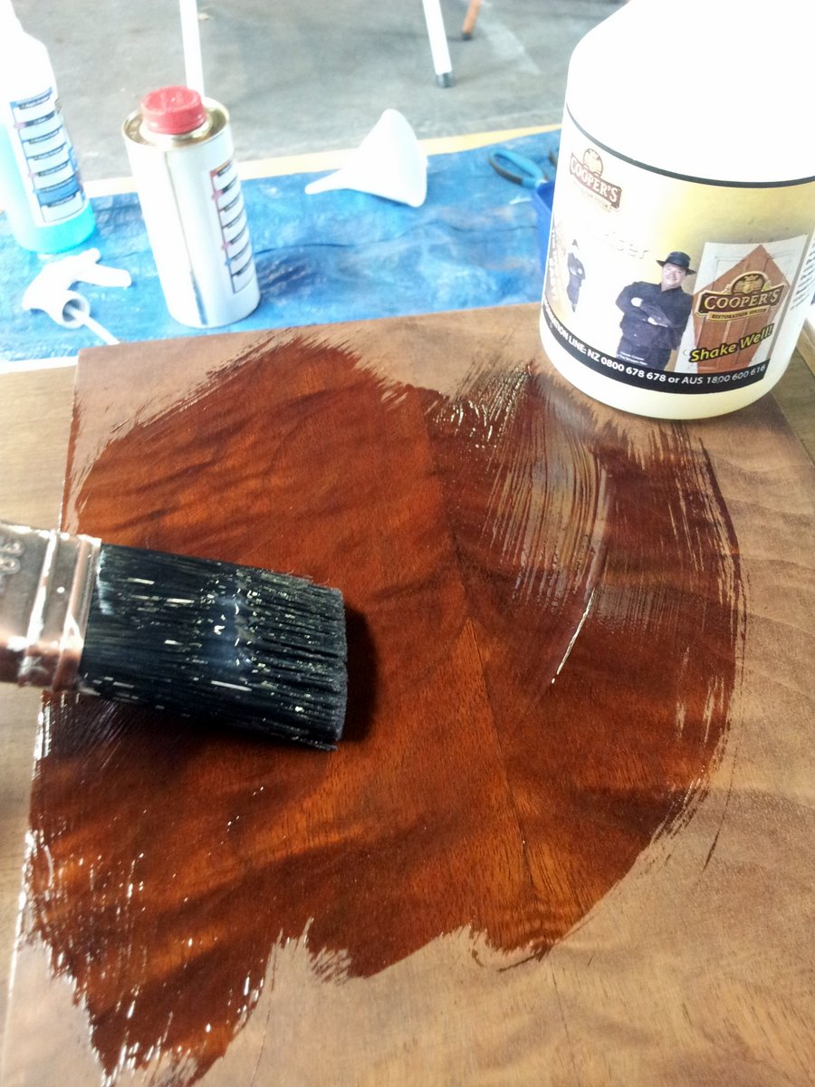
Here is me applying the stripper to the cabinet:
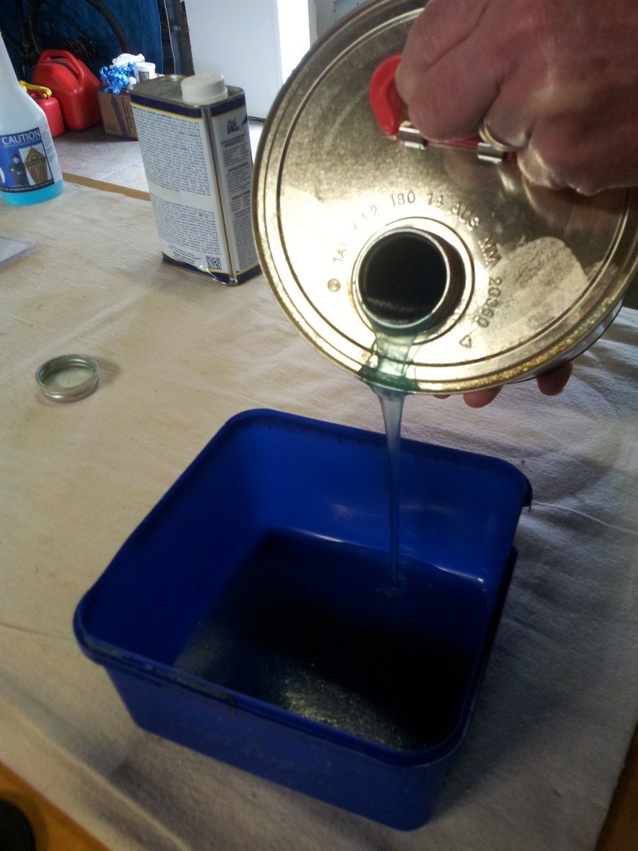 | 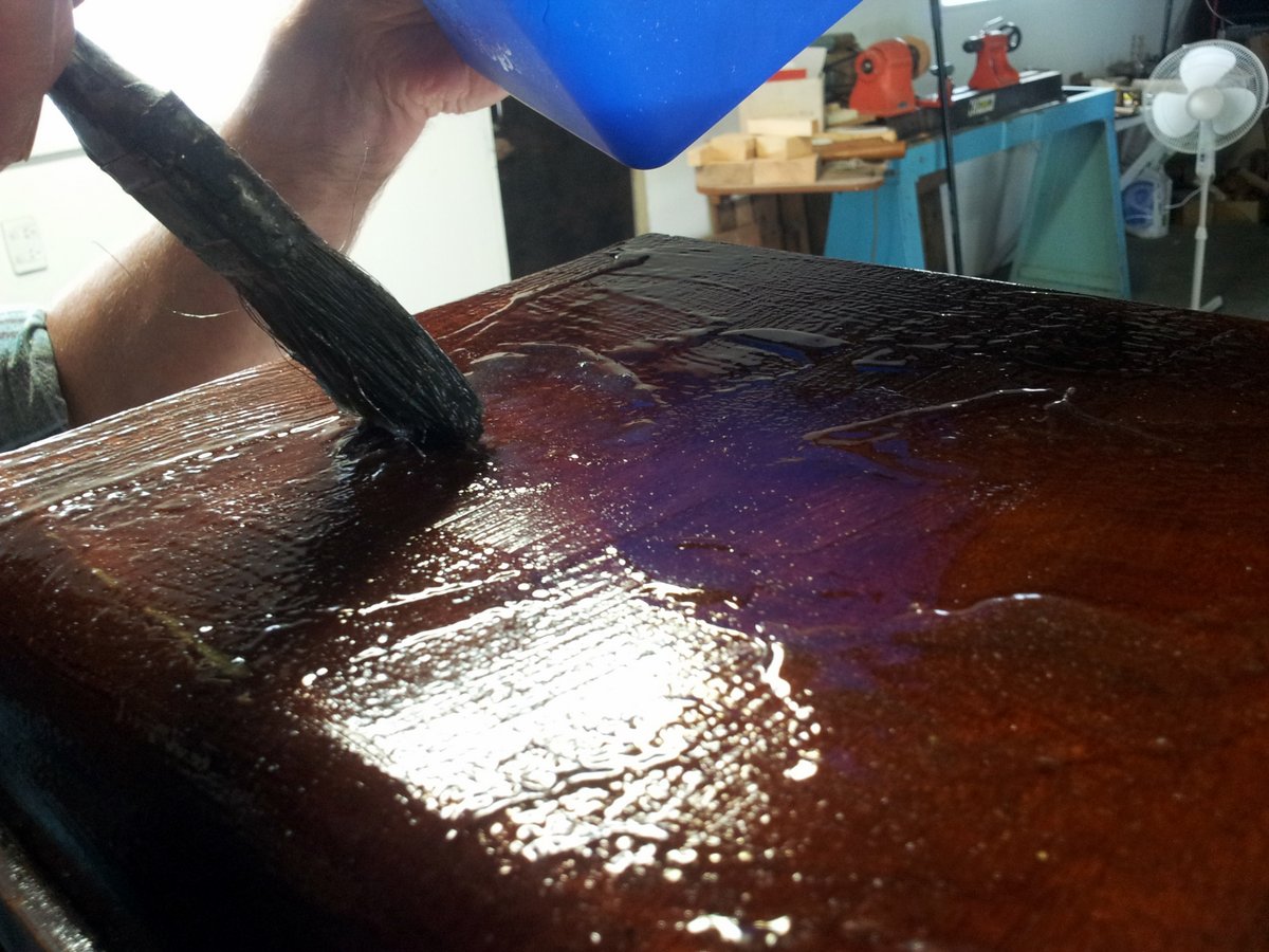 |
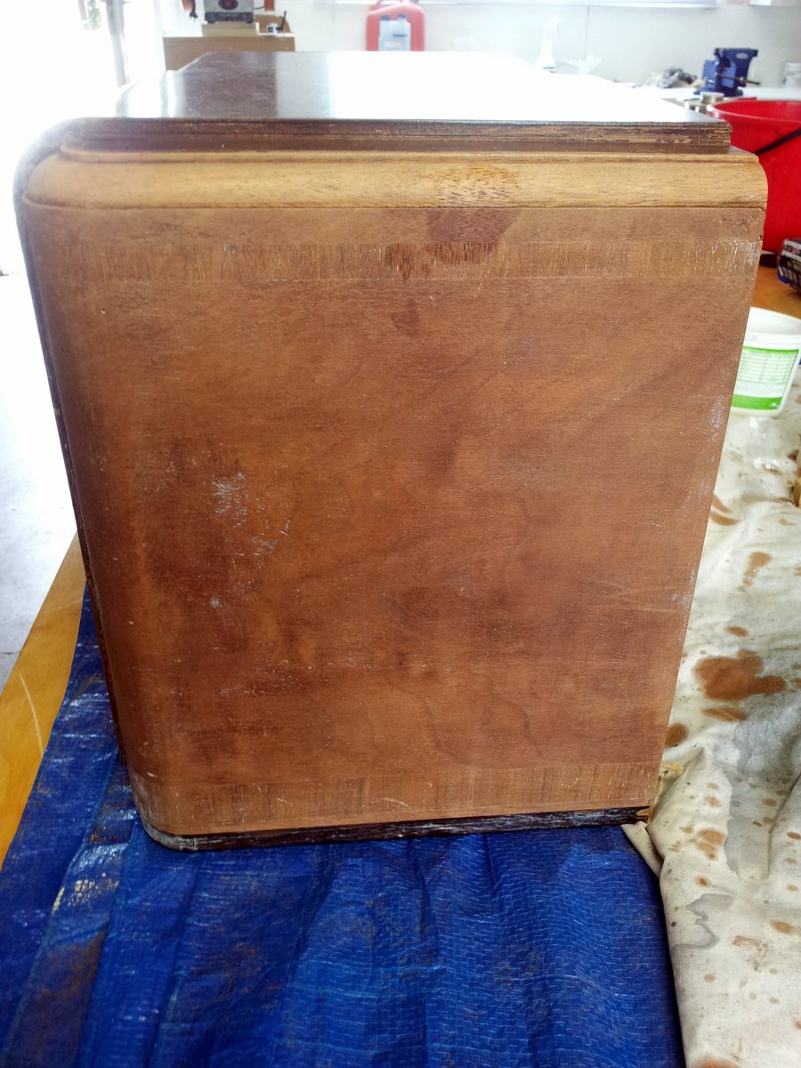
This is left for about 20 minutes, and then the stripper removed with a combination of scraping, steel wool and water/washer.
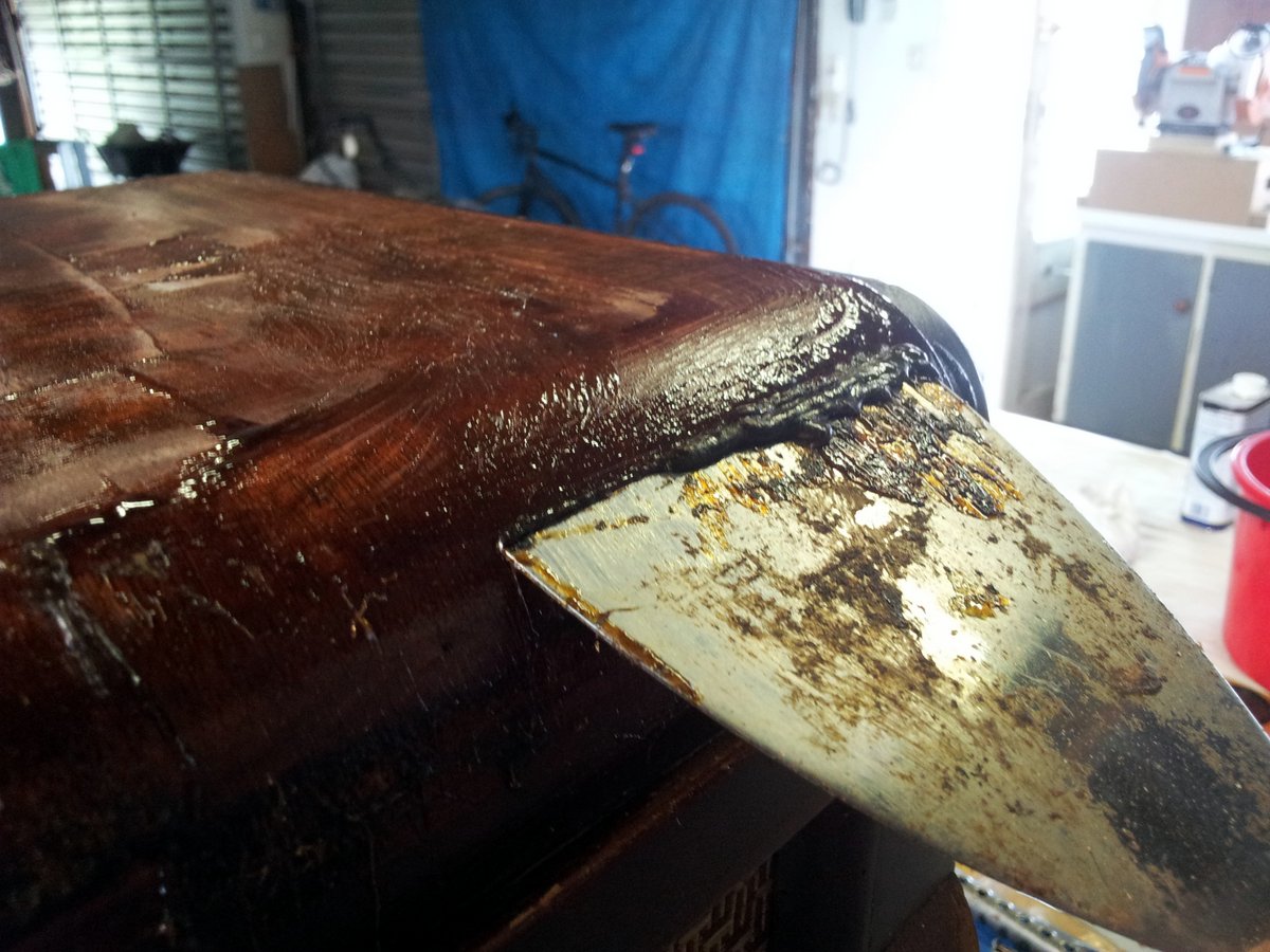
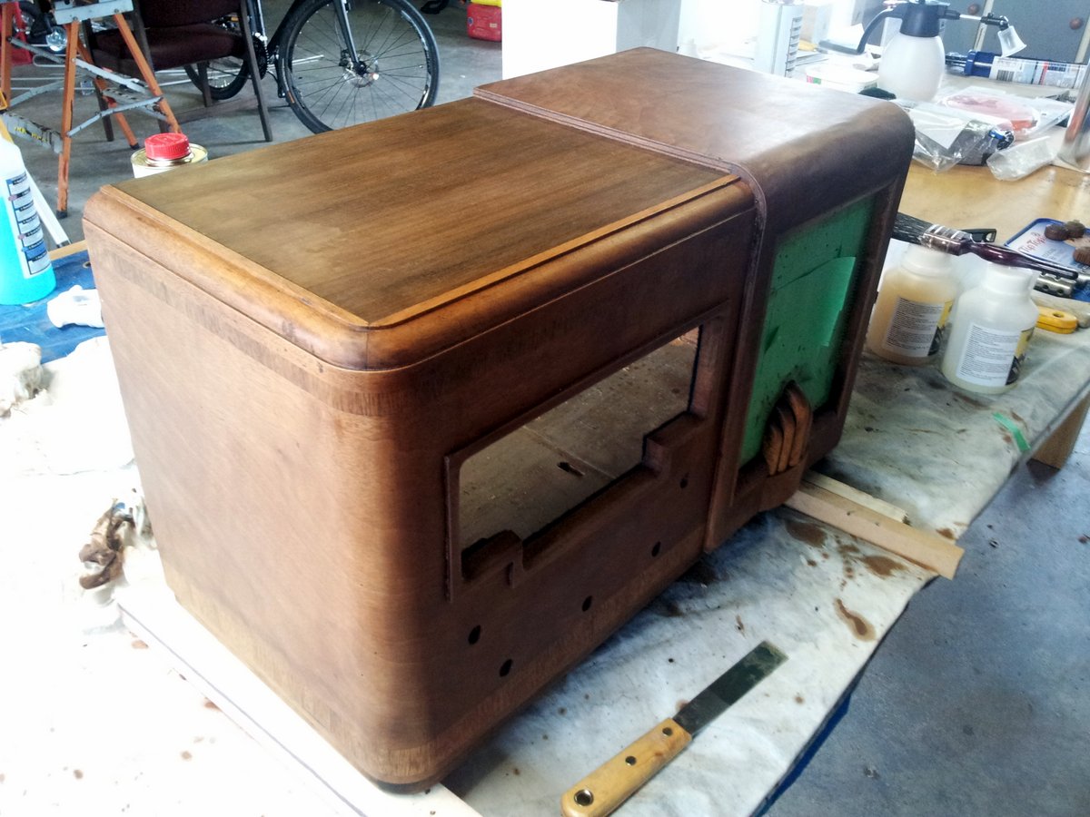
Yay, it works! You can see the bare wood (on the side) coming up nicely in the photo below:
I did a bit of a comparison between them, and the differences were pretty amazing! The Cooper’s seemed to produce a much nicer finish than the other two…
 |  |
Sadly, I also had to remove the “Columbus” logo, as there was no way of protecting it while at the same time stripping off all of the varnish surrounding it.
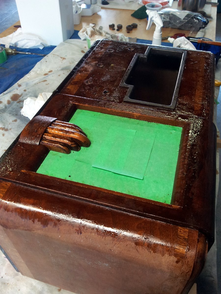
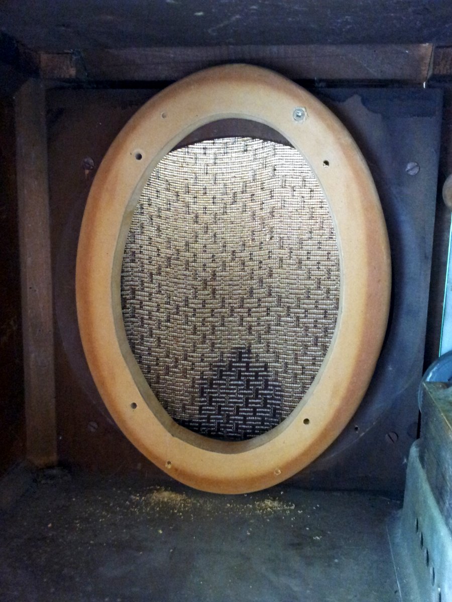
I had to mask off the speaker port while stripping the front panel.
Don’t forget to strip the dials! These had intricate carvings of the Columbus ship on them.
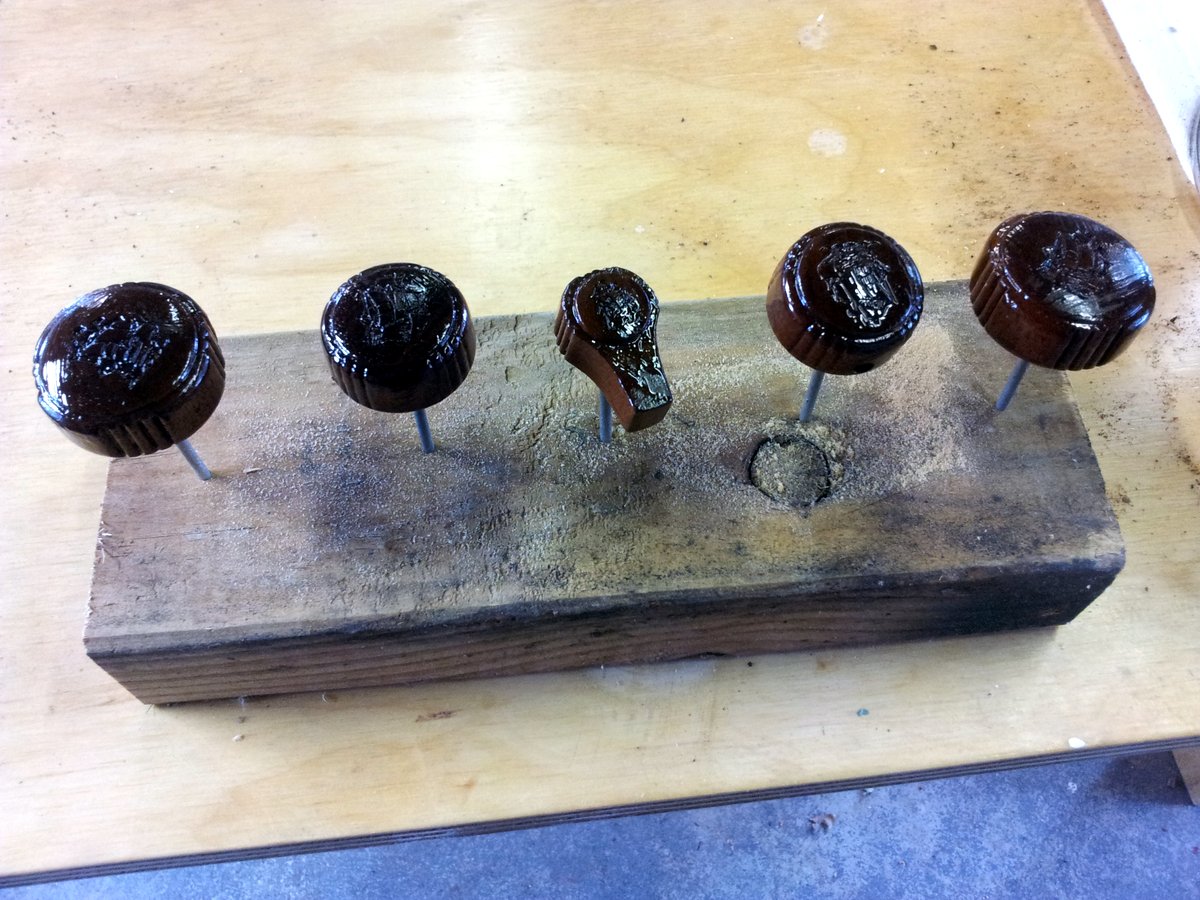
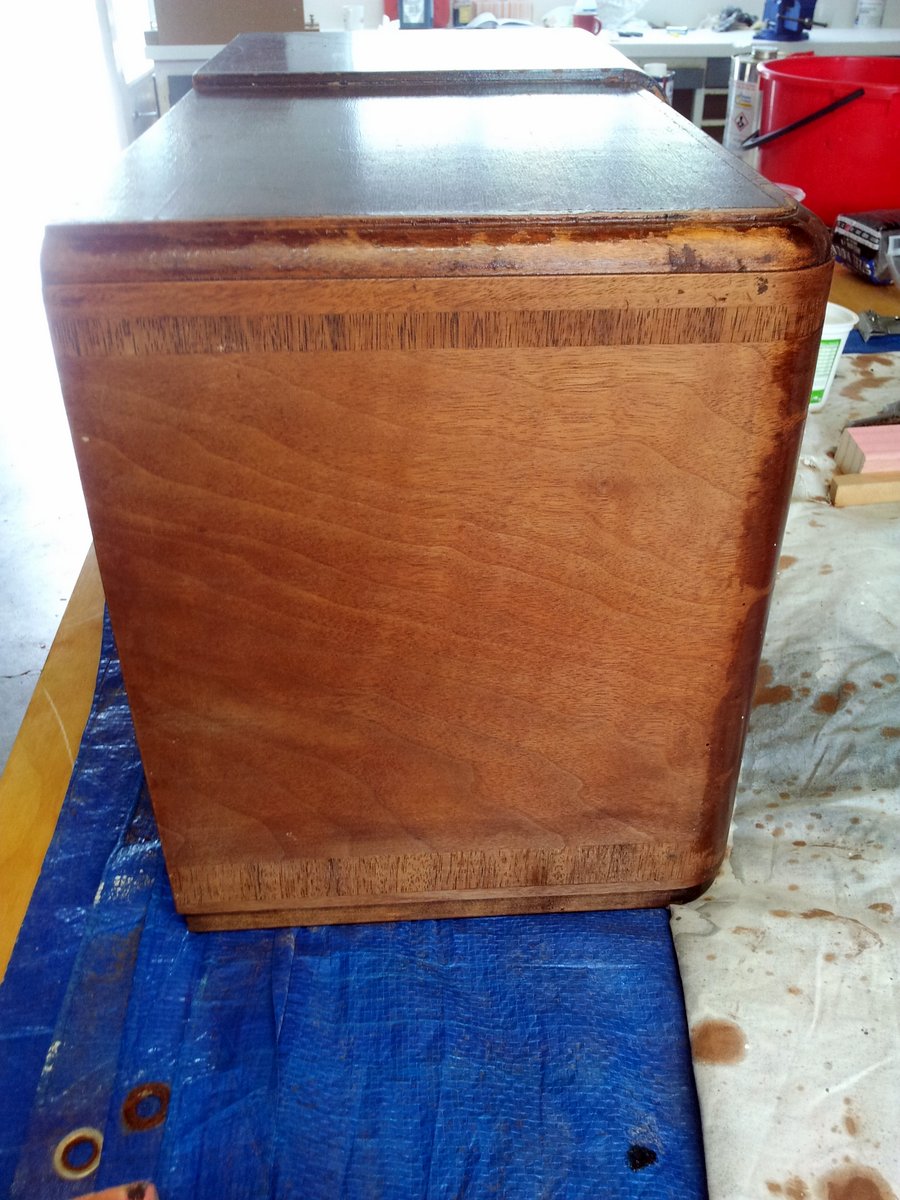
All stripped! The wood had come up really nice, and since all of the glossy, cracked varnish had gone, I realised there were far more veneer patterns than I first thought.
Moisturising The Cabinet
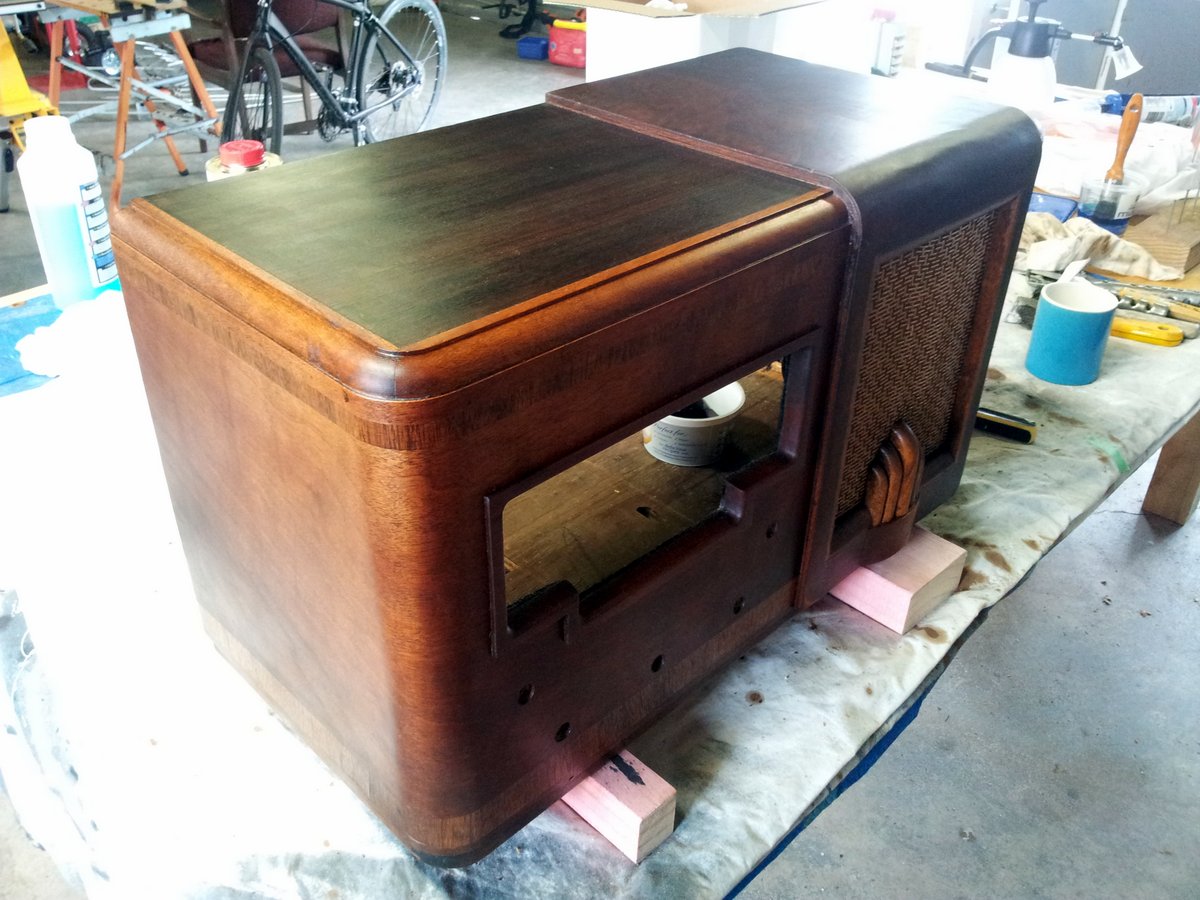
The Cooper’s “wood restoration” product line also includes some moisturiser that you are meant to add after you have stripped it.
The moisturiser does not give it a hard surface, nor does it stain the wood, but rather soaks into it and brings out the original colour.
No More Borer
The existing cabinet had quite a few appearance-degrading borer holes on the front face. To prevent any more of these, I gave the cabinet a good coat of “no borer”.
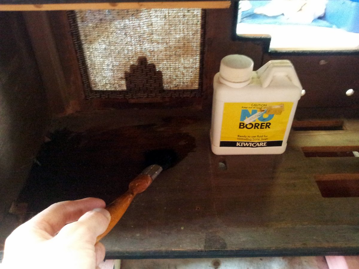
Cleaning The Glass
The glass panel had to be handled carefully, the radio frequencies and other text printed on it I wanted to keep for retro reasons, yet it looked like it would flake off at the gentlest touch.
Electronics
The Smarts
I decided on using a RaspberryPi with the Volumio distribution. I already had some Raspberry Pi experience after the Auto-Electric Blanket project and just general tinkering, and Volumio software looked like a pretty powerful and open-source music streaming application that would work on the Raspberry Pi.
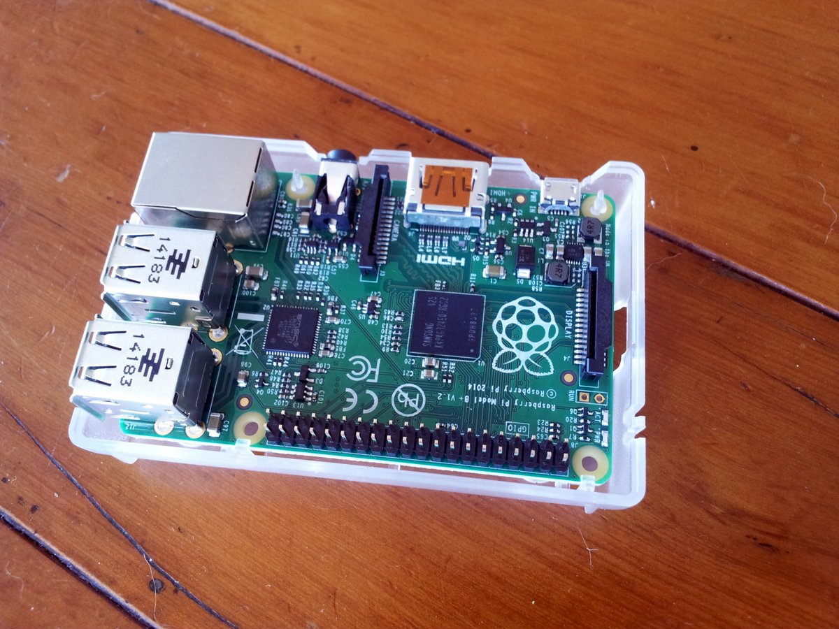
The RaspberryPi B+ was preferable over the older A or B solely because of the improved audio output. The first versions of the Pi shared a single regulator between the audio output DAC and a few other peripherals. These peripherals, when in use, caused some significant distortion/noise of the audio output. They have fixed this in the B+ and given the DAC its own dedicated voltage regulator.
Amplifier
I was initially looking at an amplifier from DealExtreme like the TA2024 or the FX502A, for about US$40-$60. However, I eventually decided to use the car stereo amplifier I pulled out of my old Ford Laser since it was lying around and doing nothing. It is a JVC KD-G396 50W(max)x4 MOSFET-based car head unit.
Speakers
I could have kept this speaker and gone for a “classic sound” as well as a “classic look”, but I really preferred something with a bit more clarity and punch, so I decided to replace the speaker with two 40W RMS 6x9 speakers I had lying around after my Ford Laser got wrecked.
Unfortunately, these didn’t quite fit side-by-side when facing forwards in the enclosure! So for better or worse, I decided to face one backwards (goodbye stereo). Here is the front speaker being installed:
 |  |
Installing the rear speaker:
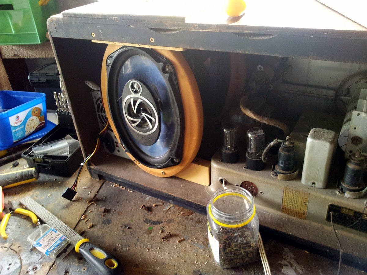
EDIT (post completion): One backwards facing speaker didn’t seem to be that detrimental (apart from not having proper stereo)! I tested various speaker configurations and there seemed to be no difference between the rear speaker facing backwards or forwards.
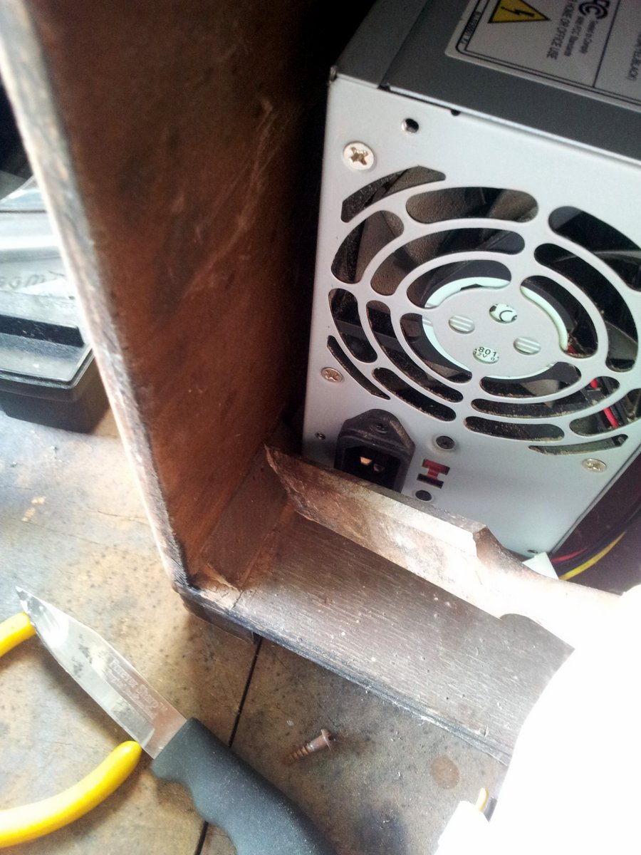
PSU
This was an easy design choice, I needed both +5V @ 500mA and +12V @ whatever speakers take (approx. 1A continuous, 5A peak per speaker, based on the speakers’ power ratings). I had some old computer ATX PSUs lying around, so chose a suitably sized one (this wasn’t hard either, there was plenty of space in the back of the Columbus radio).
LEDs Are Not Retro, Woops
There used to be some sort of valve-based indicator which poked out onto the front glass panel.
 | 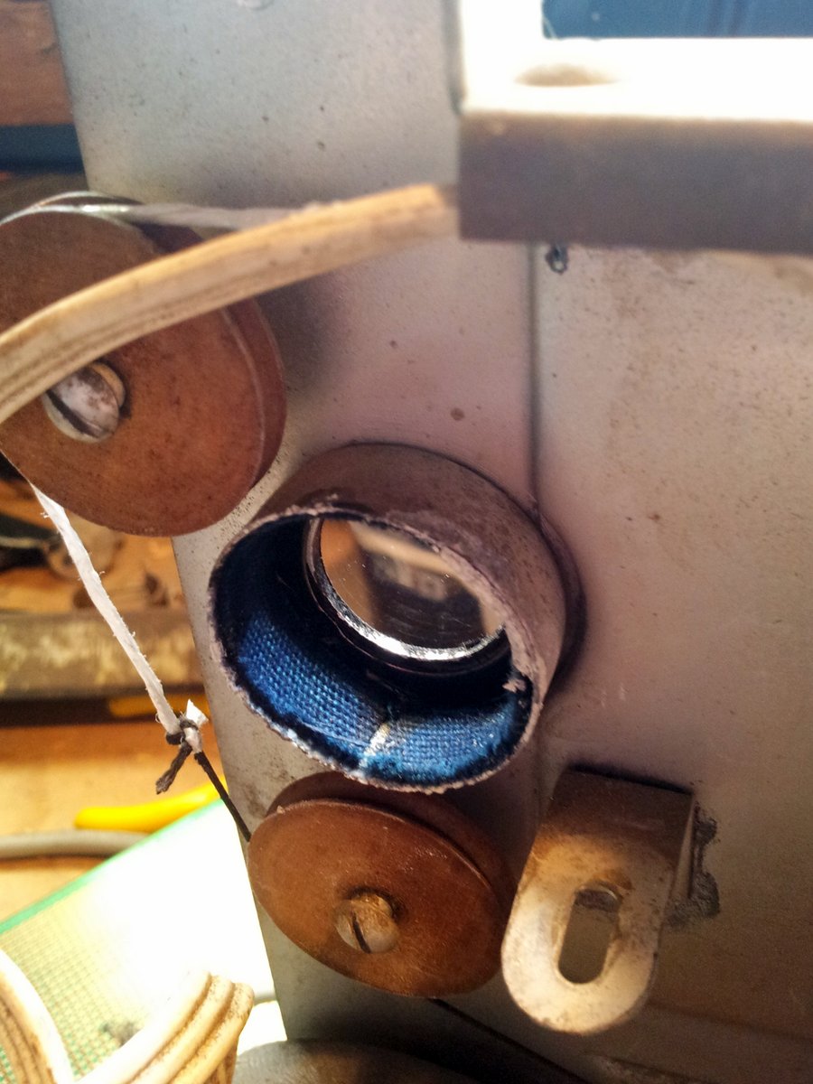 |
I got the great idea to use LEDs to indicate two things, when the power was on, and when the radio had internet connectivity. I busily spent many hours buying the high-power LEDs, working out how to diffuse their light, making a reflective backing for them to push more light forwards, and installing them into the radio. I was just glueing up the little housing I made for them with epoxy when I realised, crap, LEDs are not retro at all!
Heartbreakingly I decided to rip them out right then and there before the epoxy set, and start anew. This time I used a tungsten based bulb instead, wrapping it in black cardboard to make up a mount that would fit the original hole.
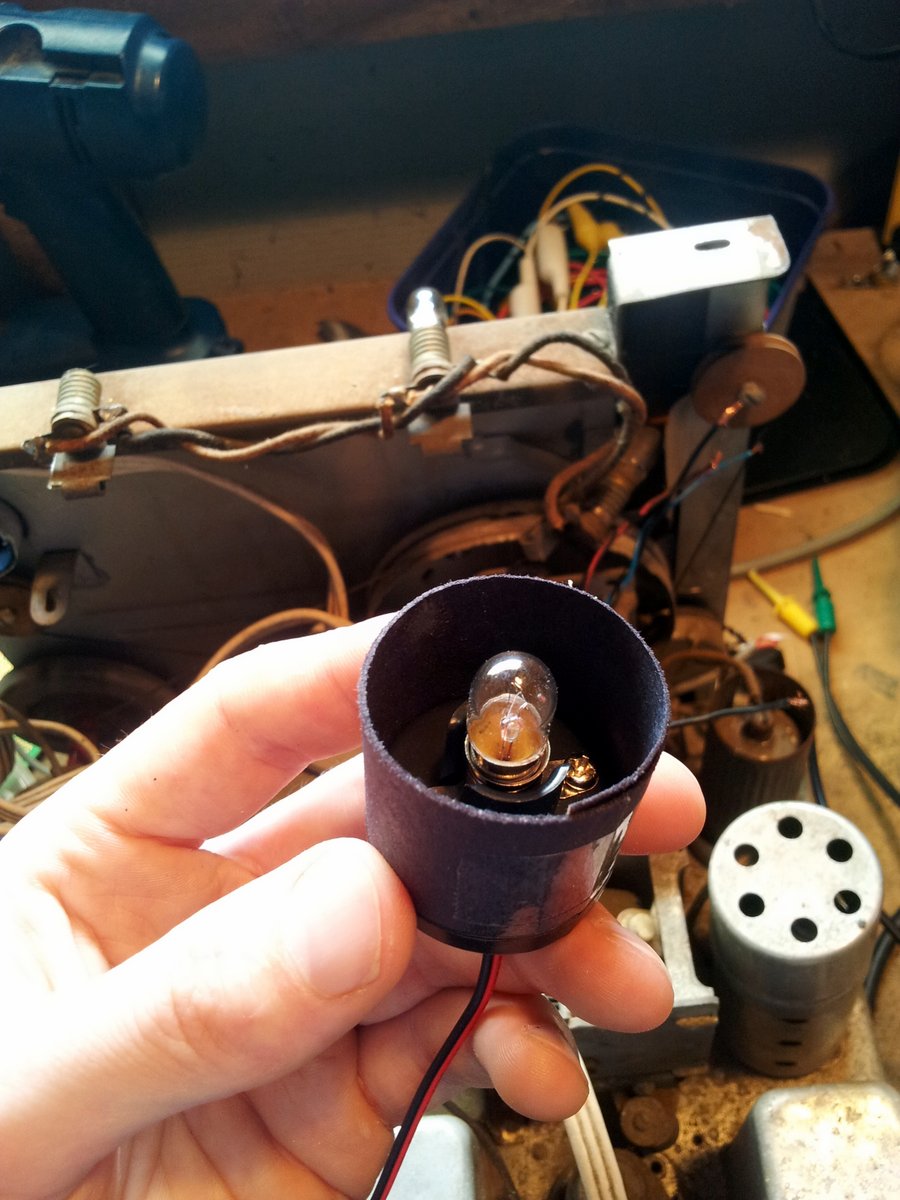 | 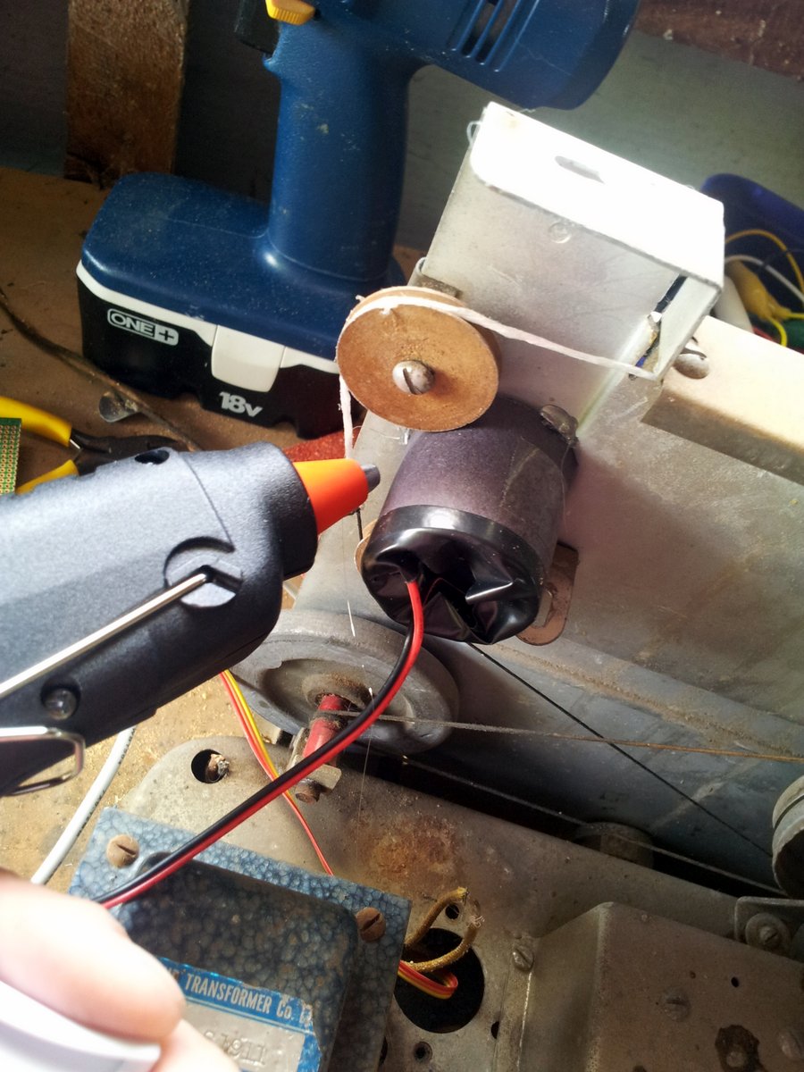 |
User Interface Inputs
Even though the unit is designed to be controlled by the Volumio web interface, I thought it would be nice to be able to turn it on/off, control the volume and skip to the next track without having to use a computer/phone.
There are 5 dials on the Columbus radio. The central one is a SPST switch for controlling the power. Then there are two potentiometers, which I’m guessing one would have been for volume, not sure on the other. Then there was one dial which controlled a pulley system that moved the plate capacitor and another dial which switched between the different radio-frequency bands.
I decided to use the two existing potentiometers to control the volume and to switch to the next track. The volume one is self-explanatory, for the “next track” functionality I had the idea to make it so you just twiddle it in any direction by at least a small threshold amount to get it to go to the next track in the playlist.
RaspberryPi Daughter Board
The RaspberryPi was not enough on its own to provide all of the I/O functionality to drive the speakers, control the lights, and read in the inputs from the volume and track change potentiometers.
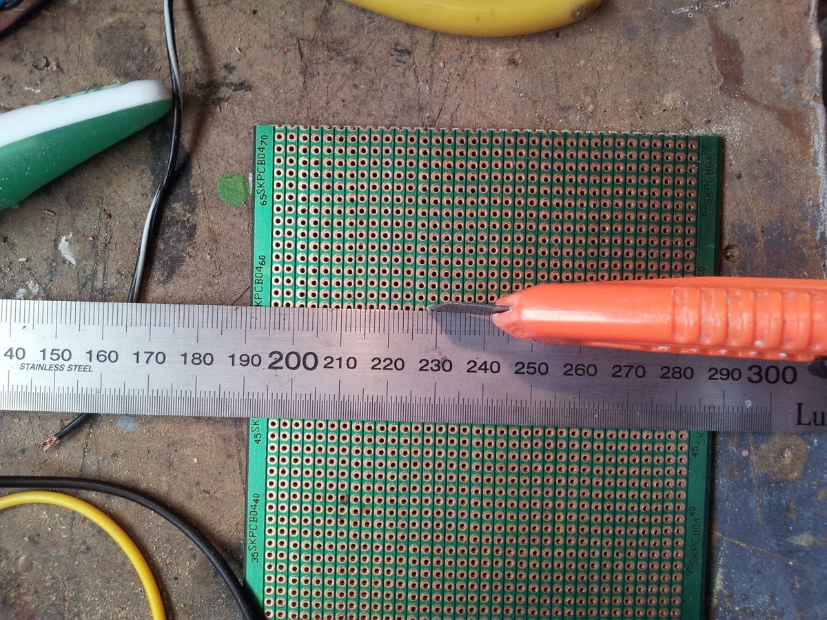
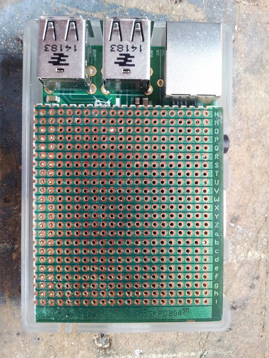
For this reason, I had to craft a daughter board. I used a piece of strip-board, shaped so that it would directly solder onto the RaspberryPi’s GPIO header, and still allow the Pi to fit inside an enclosure.
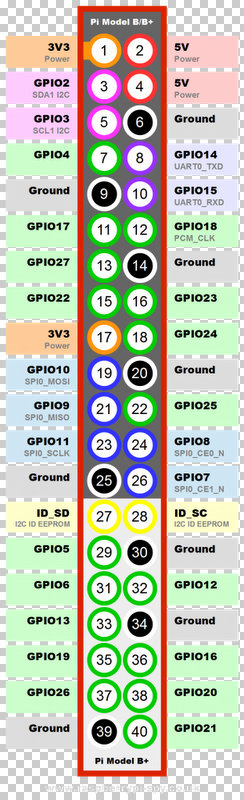
The layout of the GPIO on the RaspberryPi is shown below.
The following table shows what GPIO header pins I decided to use and what they are connected up to on the daughter board (the circuit was so simple I didn’t think it warranted actual schematics being drawn up):
| GPIO Header Pin Number | GPIO Function(s)/Name | What I Used It For |
|---|---|---|
| 11 | GPIO17 | To drive the gate of MOSFET to control the +12V, 100mA status bulb. |
| 17 | 3V3 | The MCP3008 (ADC) VCC. |
| 19 | GPIO10, SPI0_MOSI | The MCP3008 (ADC) MOSI. |
| 21 | GPIO9, SPI0_MISO | The MCP3008 (ADC) MISO. |
| 23 | GPIO11, SPI0_SCLK | The MCP3008 (ADC) CLK |
| 24 | GPIO8, SPI0_CE0_N | The MCP3008 (ADC) CS. |
| 25 | GND | Ground for the entire daughter board. |
The RaspberryPi doesn’t have any ADCs, so I had to use the popular MCP3008 ADC IC as an interface to the analogue potentiometer signals.
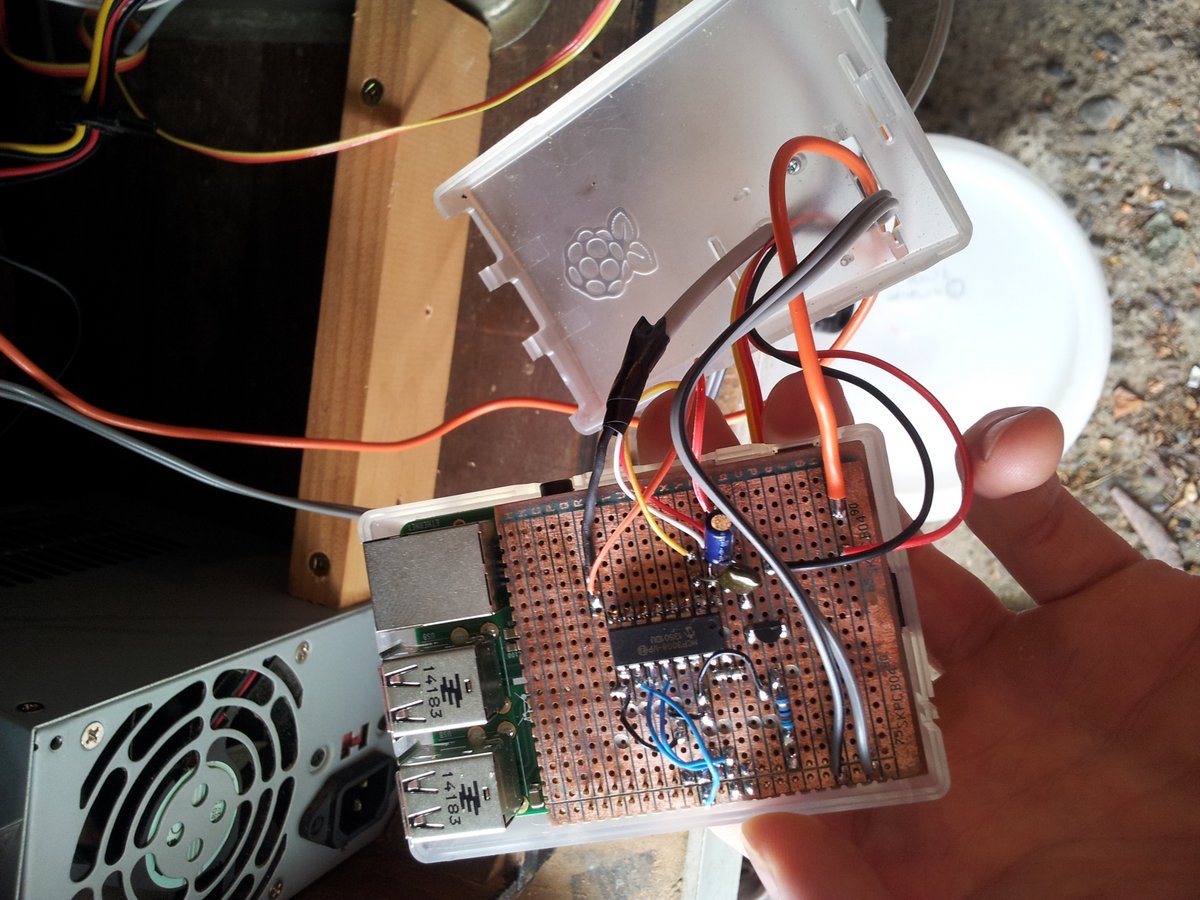
Here is a photo of the completed daughter board:
The Software
Volumio was easy to install. The Volumio v1.51 (the most recent as of 2014-12-29) image was downloaded and then written to a SD card. When the RaspberryPi is booted with this SD card and plugged into a router with an ethernet cable, you should be able to visit the Volumio WebUI by navigating to volumio.local/ on your computer’s web browser. At this point I changed the name of the device from volumio to columbus.
You can SSH into the volumio platform with the network name columbus (or whatever you changed it to), and both the username and password as volumio (type ssh columbus -l volumio, and then enter in the password volumio when prompted). If you need root access (as I did, to enable the SPI controller), you can use the same credentials as above, except replace the username with root.
The wireless was easy to setup and was working as soon as the SSID and password was entered via LAN connection. I could even change WiFi dongles and not have to re-enter this information.
Getting SPI working was more difficult. When running lsmod on the default volumio install it listed spi-bcm2708 but no spi-dev (this didn’t turn out to be an issue in the end, even though online tutorials suggest that spi-dev has to be present before the SPI will work).
I ran apt-get update and apt-get -y upgrade.
modprobe spidev seemed to run o.k. with no errors. It wasn’t listed under lsmod, but I could see the two SPI devices in /dev (run ls /dev).
Installing the spidev python module with python setup.py install. It gave me the error:
spidev_module.c:20:20: fatal error: Python.h: No such file or directorySo I installed the python development software with the command
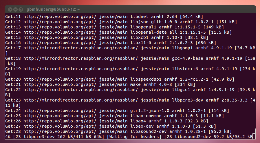
$ sudo apt-get install python-devThis took a decent amount of time to install, primarily because the download speed was a mere 50kB/s. I think this was because the RaspberryPi was connected via WiFi and was out in the garage, with low reception back to the router in the house. The fact that I even got reception was pretty impressive considering I was only using a tiny chip-antenna based USB WiFi dongle on the RaspberryPi!
This fixed the Python.h error! Now an attempt to read the ADC value.
Even though the potentiometer wasn’t moving, the read back ADC values kept varying as shown in the below image.
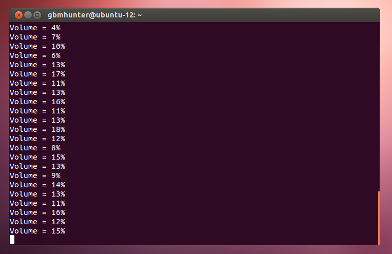
I had a feeling this was due to the high resistance of the volume potentiometer, its full scale value is 870kΩ. The input impedance of the ADC channel upon measuring must have been low enough compared to the potentiometer resistance to cause the ADC voltage to fluctuate during measurement. I fixed this jitter by adding a 470nF, 50V electrolytic capacitor on the ADC channel 0 input as close to the ADC IC as possible. My first attempt with a large 47uF capacitor didn’t work because it took too long to charge (time constant RC is too big)!
The potentiometer for the “next track” functionality also had this issue, except much worse, because its full-scale resistance was 8MΩ. I had to add a smaller 10nF capacitor otherwise again, it would take too long to charge. However, because I was using this pot to implement a binary “next track” or “not next track” command, I could easily increase the thresholding in software to get rid of false triggering.
Sending MPC Commands
My first attempt at writing mpc on the command-line gave me this error:
root@volumio:/etc# mpcerror: Connection refusedAnd then I discovered that the web interface had stopped working. Oh oh. I tried a number of things like restarting the MPD server and trying the following shell commands:
sudo /etc/init.d/mpd stopcd /var/lib/mpdls /var/lib/mpdrm -i statesudo rebootHowever, nothing seemed to fix it. I ended up having to reflash the SD card and start again.
Maybe the apt-get -y upgrade command is screwing things over, I noticed this as part of its long, long output.
Checking init scripts...WARNING: init script for nginx not found.There is also this message, where I chose “N” (keep currently-installed version).
Configuration file '/etc/monit/monitrc' ==> Modified (by you or by a script) since installation. ==> Package distributor has shipped an updated version. What would you like to do about it ? Your options are: Y or I : install the package maintainer\'s version N or O : keep your currently-installed version D : show the differences between the versions Z : start a shell to examine the situation The default action is to keep your current version.So I had to reflash again. At which point the OS wouldn’t even boot. Some issue with the SD card image?
Fixed! Had to clone all the files from the Volumio git repository back into /var/www. Volumio then prompted that there were updates available, and would you like to upgrade. After clicking yes, we were back to normal!
Also tried sudo rpi-update (and then a reboot). This also didn’t work.
The Way That Worked
So I gave up on sudo apt-get update, and apt-get -y upgrade as they seemed to break the Volumio Web UI. Given I couldn’t run the proper SPI code without running that command, I luckily discovered a bit-banged python code module (https://learn.adafruit.com/reading-a-analog-in-and-controlling-audio-volume-with-the-raspberry-pi/script) that can talk to the MCP3008.
I also found instructions on how to install the python RPi.GPIO module without having to use sudo apt-get install python (which required the sudo apt-get update call first).
wget http://sourceforge.net/projects/raspberry-gpio-python/files/raspbian-wheezy/python-rpi.gpio_0.5.8-1_armhf.debAnd then to install it:
sudo dpkg -i python-rpi.gpio_0.5.8-1_armhf.debI copied all of the custom code to the RaspberryPi using the command (note this is after changing the “name” of the Volumio platform from volumio to columbus):
rsync -avz /home/gbmhunter/GoogleDrive/Projects/ColumbusRadio/repo root@columbus:~/ColumbusRadio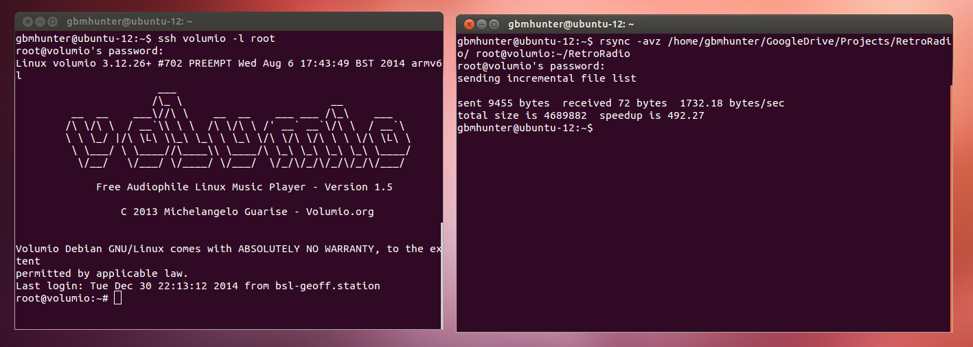
The Python Hardware UI Script
Volumio took care of the web interface, but I still needed some code to control the dials and bulb. I decided to use Python as there was no compiling needed and it allows for pretty quick development.
I originally went for a basic mega main-loop code architecture. The basic tasks I had to perform were:
- Read the ADC values from the MCP3008 to find out where the two potentiometers are. Implement filtering and thresholding for these values to prevent false triggering and jitter. Based on these readings, send the appropriate commands to Volumio to change the volume and skip to the next track.
- Regularly check for an internet connection, and start flashing the UI bulb if no internet connectivity is found.
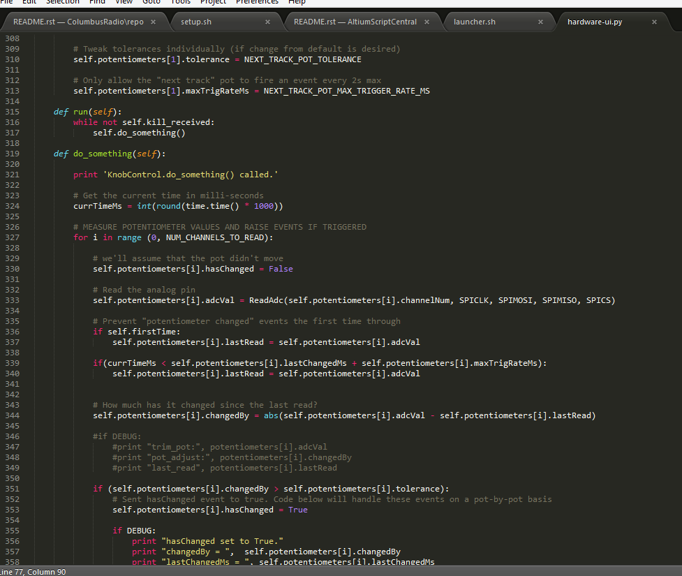
Note that the complete hardware UI code can be found in the GitHub ColumbusRadio repo at hardware-ui/hardware-ui.py.
I was discovering that the main loop lag introduced when checking for an internet connection was disrupting and causing errors in my potentiometer control code. As much as I didn’t want the extra complexity/bugs/troubleshooting time, I decided at this point that I would have to implement threading (it was a good excuse for me to learn more about python’s threading abilities).
Although getting a thread to start running was pretty trivial, getting multiple threads to exit gracefully when Ctrl-C was pressed (or the script exits in any other way for that matter), was a little more difficult.
I followed this tutorial on regexprn.com for the most part, but discovered the example code was buggy, and Ctrl-C was not causing all the threads to exit! I had to modify the code example by replacing:
try: threads = [t.join(1) for t in threads if t is not None and t.isAlive()]with:
for i in range(len(threads)): # Make sure thread still exists if threads[i] is not None: print 'Attempting to join()...' threads[i].join(1) if threads[i].isAlive() is False: print 'isAlive() is False, removing thread from list...' threads.pop(i)After I did that, the threads started working correctly! I had one thread for controlling the two potentiometers and sending commands to volumio, and one thread for monitoring internet connectivity and controlling the bulb (the bulb flashes slowly with a period of 4s if there is no internet connectivity).
Getting The Hardware UI Script To Run On Startup
I needed the hardware UI script to run automatically whenever the RaspberryPi booted up. To do this I created another small bash script called launcher.sh that ran the python hardware UI script.
sudo python ~/ColumbusRadio/hardware-ui/hardware-ui.pyThis launcher.sh script was added to the root user’s crontab with the command:
# Write out current crontabcrontab -l > mycron# Echo new cron into cron fileecho "@reboot sh ~/ColumbusRadio/hardware-ui/launcher.sh ~/ColumbusRadio/hardware-ui/cronlog 2>&1" >> mycron# Install new cron filecrontab mycron# Remove temp cron filerm mycroncrontab would start the script on startup of the RaspberryPi, and it would run under the user root (which is good, because we have got all privileges, and means we don’t have to use sudo all the time).
Power Supply Woes
During prototyping/testing, the red power LED on the RaspberryPi kept flashing. I discovered that this was mainly due to a large dropout between the USB wall-charger and the RaspberryPi’s +5V lines! And this was when the device was only drawing about 300mA max.
I fixed this by powering the device through the USB port from a bench-top power supply, and shortening the USB lead. I had to turn up the benchtop power supply voltage to +5.3V (ouch, not a good practice people!) to bring the RaspberryPi’s +5V line up to 5V.
This didn’t turn out to be an issue in the final product, as the RaspberryPi was powered directly from the PSU’s +5V. It was also powered directly to +5V on the GPIO header, meaning it bypassed the low but still significant resistance between the USB VBUS and the +5V rail. This came at the expense of bypassing protection circuitry. Hopefully the PSU doesn’t inject any voltage spikes onto the rail!
The End Result
Here is a photo of the finished media-streaming, internet aware radio!

Statistics
Everyone loves statistics, right?
At A Glance
| Project Start Date | 2014-12-06 |
| Project End Date | 2015-01-02 |
| Total Hours | 68.5 |
| Total Cost | NZ$401 |
| Lines of Code | 564 |
Time Statistics
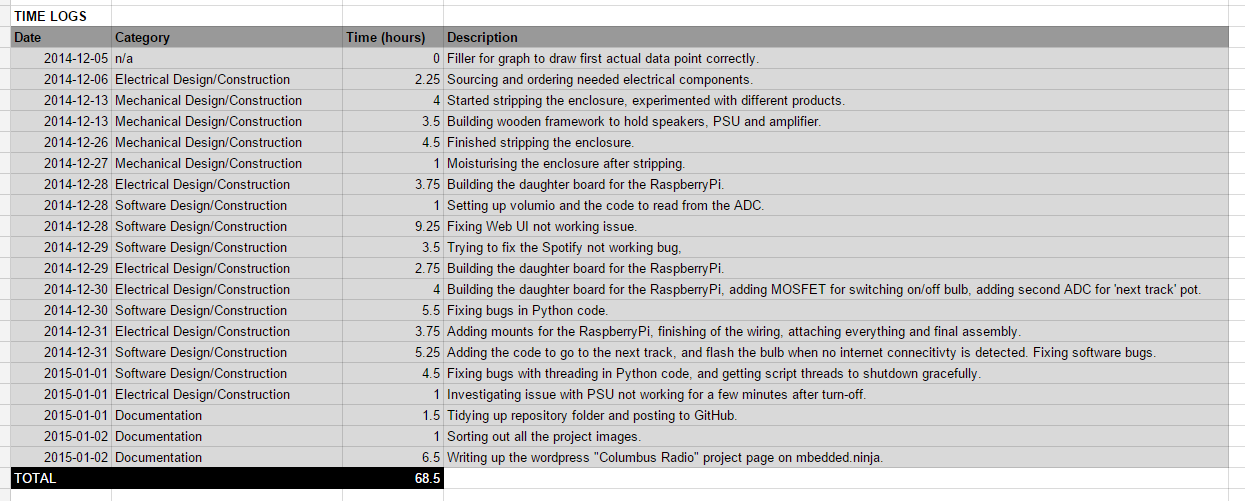
Below are the time logs for this project:
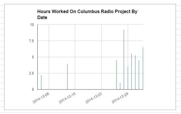
The time spent (in hours) by date:
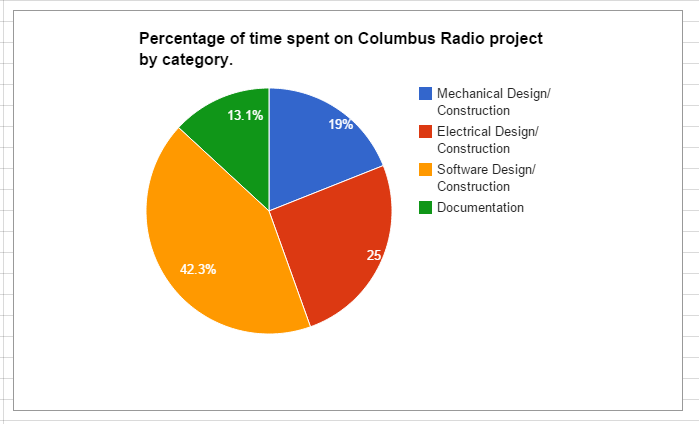
The time spent on the Columbus Radio project (as a percentage) by category:
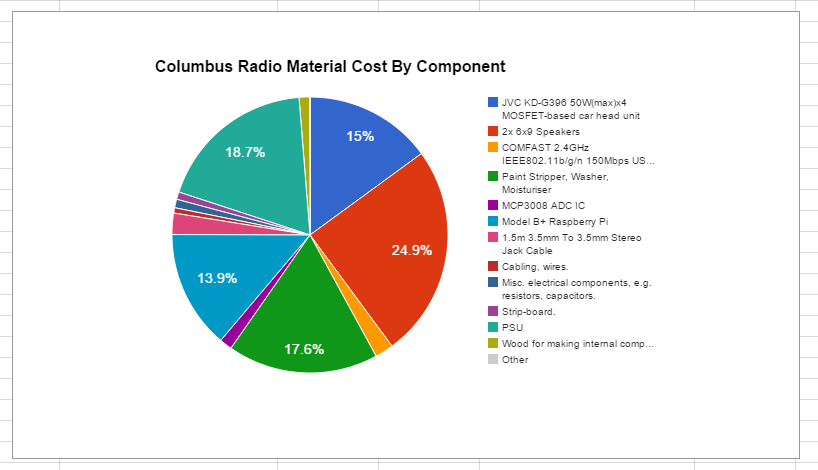
Material Cost Statistics
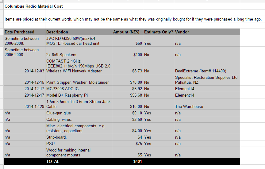
The individual material costs of each item used to build the Columbus Radio.
And now as a pretty pie chart (as a percentage of the total cost):
Things To Improve On
- The volume control dial is very sensitive, and the volume only changes a distinguishable amount over a small segment of the potentiometer’s full range of motion. I believe this a compounded problem due to the potentiometer itself being logarithmic, but the code treating it like a linear pot, and the volumio volume control being quite sensitive in the upper volume regions to start off with.
- If you pull the radio’s power cord out from the wall (or turn it off at the wall), you have to go around the back and set up the head unit to the correct volume and sound source (aux). The head unit is designed to have the continuous power source from the battery when in a vehicle, a battery that the radio does not have. Turning the radio on/off by its front on/off switch does not cause this problem as I leave a residual power feed on that goes to the head unit. Unfortunately this means that the PSU and RaspberryPi also continuously run, which may shorten their life and definitely consumes more mains power than necessary!
- Simultaneous playback. It would be really neat to have other devices around the house that can be set up to play the same song at the same time. I’m guessing this feature would be best built into the Volumio player that I am using.
- The software does not turn itself off when the power switch of the radio is turned off (the power switch just turns off the amplifier). This is a good thing in terms of start-up speed, as music is pretty much instantly available as soon as you turn it back on. However, it does mean that volumio keeps streaming music from the internet, which can chew up bandwidth if you have a long playlist and/or set it into repeat mode. A better way would be for the power switch to also pause the music, and then start it again when it turns back on, starting off from where you left it.