Unbricking a nRF53 Due To DCDC Config

Unfortunately, you can quite easily “brick” a Nordic nRF53 series microcontroller if you both:
- Are using the newer nRF Connect SDK (based on Zephyr), and don’t explicitly disable the DCDC converters in the
proj.conf. - Don’t fit the inductors required for the internal DCDC converters (also called Switch-mode Power Supplies, or SMPS), because you plan on using the LDO (low dropout linear regulator) instead.
In this scenario, if you forget to explicitly disable the SMPS in the Zephyr prj.conf file, then the SMPS will be enabled (yes — they are enabled by default). But you don’t have the required inductors, the SMPS will not work, and the internal voltage rails required by the MCU will not do anything but stay at 0V. This unfortunately “bricks” the MCU. You can’t re-program the device with a fixed firmware binary because the MCU requires these internal voltage rails for programming.
# Disable all three internal SMPSs.# WARNING: Do NOT remove these lines, doing so will brick the MCU,# as it expects the inductors to be fittedCONFIG_BOARD_ENABLE_DCDC_APP=nCONFIG_BOARD_ENABLE_DCDC_NET=nCONFIG_BOARD_ENABLE_DCDC_HV=nRecovery
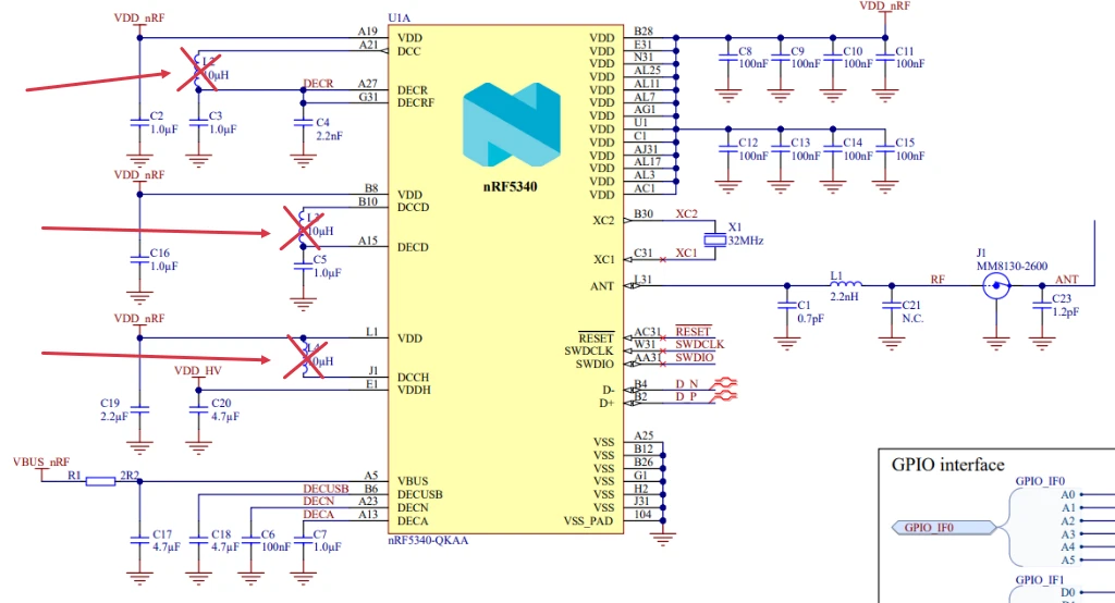
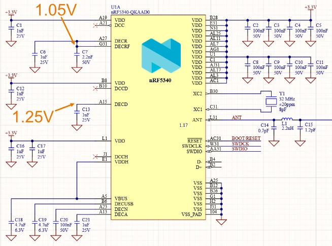
However, you can recover from this by providing the required power rails externally. All you need to two extra benchtop adjustable power supplies and access to the right pins. Luckily, even when not attaching inductors, the design guidance from Nordic recommends you add bulk capacitance to these pins away, giving you a good point to solder wires onto.
- Provide 1.25V to the
DECDpin - Provide 1.05V to the
DECRFpin
This is a placeholder for the reference: fig-schematic-showing-where-to-apply-voltages shows a schematic of a nRF53 SoC showing which pins to apply these voltages to.
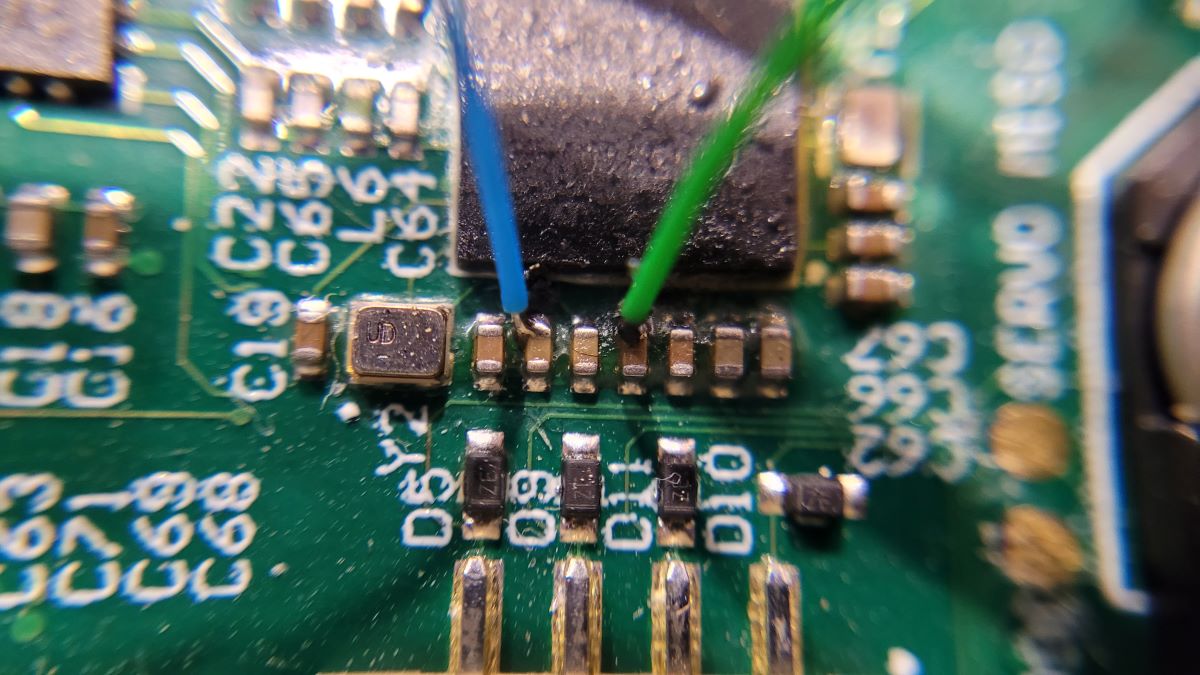
This is a placeholder for the reference: fig-soldered-wires-to-nrf53-to-provide-two-voltage-rails shows a photo of two wires soldered onto the bulk capacitance on these two power rails. These two wires go off to external power supplies (ground is connected via a ground test point elsewhere).
Once you’ve powered these rails (along with providing power to the standard input power pins on the MCU), you should be able to connect to the device again using a programmer. At this point all you need to do is to flash it with firmware which disables the DCDC converters (or just erase the device). Then you can remove the external voltage supplies and wires and you’re back in action!