Digital-to-Analogue Converters (DACs)

Architectures
When looking for a DAC for your next project, you might stumble across a few different DAC types (or architectures). Whilst they all achieve the same basic end goal of converting a digital value into an analogue one, it pays to understand the different internal designs to choose the one that best suits your need. The most common DAC architectures are:
- String DAC (Kelvin Divider DAC)
- R-2R DAC (Voltage Switching DAC)
- Multiplying DAC (MDAC)
- Delta-Sigma
Any of these architectures can be unipolar or bipolar. Unipolar (a.k.a. single supply) DACs only convert digital values into either positive or negative values, while bipolar DACs can output both negative and positive output values.
We will discuss these further in the following sections.
String DAC (Kelvin Divider)
The string DAC (a.k.a Kelvin divider DAC) is the easiest DAC design to understand, and is just a string of equal-valued resistors from to , with taps off each junction to the output.

A bit string DAC requires resistors. This is a sensible number for lower resolutions of 8-10 bits, but soon gets prohibitively high for higher resolutions. For example:
- 8bit DAC: 255 resistors
- 10bit DAC: 1023 resistors
- 12bit DAC: 4095 resistors
- 16bit DAC: 65535 resistors!!!
A string DAC is very dependent on well matched resistors to achieve good linearity. A string DAC has low glitch error.
R-2R DAC (Voltage Switching DAC)
The R-2R (or R-2R ladder) architecture achieves high resolution using only two resistor values ( and ), needing far fewer resistors than a string DAC of the same bit count.
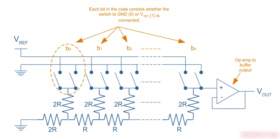
A bit R-2R DAC requires resistors1.
A R-2R DAC can have large glitch errors, due to timing differences in the switches which connect junctions to either or .
MDAC
The MDAC architecture is very similar to the R-2R architecture.
Delta-Sigma
Delta-Sigma (or Sigma-Delta) DACs provide the highest precision DACs compared to any other common architecture. You typically find Sigma-Delta DACs with a resolution of 18-24 bits.
Output Types
- Buffered voltage outputs: The output from the digital-to-analogue conversion circuitry is fed into an op-amp to buffer the circuitry, lowering the output impedance and making the output less sensitive to current draw and noise.
- Unbuffered voltage outputs: No op-amp is added to buffer the output voltage.
Voltage References
The voltage reference is a very important piece of a DAC circuit. The voltage reference provides the full-scale voltage that the DAC will output (or a fixed multiplier of the full-scale output if there is an output buffer with multiplier). It is important to consider the accuracy of the voltage reference over temperature changes. Typically an error in is provided, with a value of being normal.
Internal Voltage References
Many DACs come with built in internal voltage references (as well as allowing you to connect an external voltage reference if required).
External Voltage References
Most DACs have a requirement for the external voltage reference to be no less than approx. 1V.
Datasheet Specifications

Resolution
This is normally given as the number of bits. This determines what the smallest output step change will be in-response to the smallest digital code change (and change in the LSB). For example, a 10-bit DAC will have 2^10=1024 steps, and so the smallest output step change will be 1/1024 of the reference voltage. Not to be confused with accuracy.
Monotonicity
Typically when specified as a number of bits, this is the number of bits which are guaranteed to give a monotonic increase in the output voltage. Monotonicity is when the output always increases or stays the same (never decreases) as the digital codes increase. For example, a 16-bit DAC may have monotonicity guaranteed for the first 12 bits (MSBs).
Zero Code Error
Voltage when the DAC is instructed to output 0V (the zero code). Typically 0.5-10mV. In a unipolar DAC, this is the same as the offset error. In a bipolar DAC, this is different to the offset error.
Offset Error
The difference between the ideal output and measured output at the lowest possible voltage. For a unipolar DAC the lowest possible voltage is 0V, so this is the same as the zero code error. For a bipolar DAC, this will be the most negative voltage and different from the zero code error.
Output Power-Up Voltage
Within a family of DACs, sometimes there are different physical variants of the IC which will output different voltages on power-up. The most common output voltage is 0V on start-up.
DC Output Impedance
Most buffered output DACs will be able to sink/source current (push/pull) and so the output impedance will be applicable over a negative and positive current ranges. Typically 50-200mΩ.
Integral Non-linearity (INL, aka Relative Accuracy)
Integral non-linearity (INL, also called relative accuracy) is a measure of the difference between the actual output voltage and ideal output voltage for a particular digital input code. It is measured after offset and gain errors are compensated for. To compensate for this, the typical “ideal output voltage” is to determined. Confusingly, there are two different ways the “ideal output voltage” may be calculated:
-
End point line: A line through the minimum and maximum output voltages of the DAC. The error will be 0 for the first and last points. Sometimes, because of additional errors near the end-points, the line is taken between two codes offset from the extreme limits of the DAC. For example, the 12-bit Texas Instruments DAC7678 DAC provides a relative accuracy measured by a line passing through codes 30 and 4050 (with code 4095 being the upper-limit for a 12-bit DAC)2.
-
Best fitting line: A line fitted using linear least-squares regression.

If the INL is given in bits, this is achieved by dividing the INL in volts by the voltage of the LSB.
For example, if the was 4.3mV, the DAC was 10-bit and went from 0V to 2.5V, then:
Differential Non-linearity (DNL)
Differential non-linearity measures the deviation from ideal in two analogue output values corresponding to two adjacent digital input values. For example, if the analogue output voltage changes by 1.2LSB when the digital input increments by 1LSB (the smallest step size), then the differential non-linearity is 0.2LSB. The value specified in the DAC datasheet is the worst-case differential non-linearity for any input step change.
The differential non-linearity for any step is given by:
And then the value given on the datasheet is just the maximum across the whole operating range:
A differential non-linearity of more than 1LSB may lead to a non-monotonic transfer function (a.k.a. missing codes).
Total Unadjusted Error (TUE)
No, DACs do not have more error on a Tuesday. Total unadjusted error (TUE) is an error metric of a DAC which combines the INL, gain and offset errors into a single metric.
This equation only holds true if the three noise sources are uncorrelated and each follow a normal distribution.
Glitch Energy
Ideally, the output of a DAC would move smoothly from one voltage level to another when the input code is changed. In reality, because the output voltage is determined by discrete switching elements, and each switching element may have slightly different switching times, the output voltage can swing/spike to unexpected voltages while the DAC is transitioning. Even if the internal DAC switches could switch instantaneously, they may be purposely designed with break-before-make behaviour to prevent current shorts in the internal circuitry (very similar to the concept of dead-time in a H-bridge). Resistor ladder DACs have small glitch energies, while R-2R DACs produce large glitch energies.
A simple way to reduce the glitch energy is to add a large capacitor on the output of the DAC. This capacitor, driven by the output impedance of the DAC, will create a low-pass filter and reduce the amplitude of the glitch. However, this capacitor can also slow the settling time of the DAC, which might be undesirable in high-frequency applications.
Another way to reduce the glitch energy is to add a external track/hold amplifier to the output of the DAC. This method can almost completely get rid of any glitching, however it requires additional circuitry and complex timing control between the DAC and track/hold amplifier3.
Manufacturer Part Families
- AD5: Analog Devices’ main range of DACs (the
AD7prefix is mostly used for their ADCs).- AD5683: 16-bit, single-channel, buffered voltage-output DAC with SPI interface.
- LTC: Range of DACs by Linear Technology (now owned by Analog Devices).
- LTC2664: Quad 12-/16-bit voltage-output DAC with integrated reference.
- DAC: Texas Instruments’ range of DACs.
- DAC7678: 12-bit, octal-channel, voltage-output DAC with internal reference.
Footnotes
-
Walt Kester. MT-015 Tutorial: Basic DAC Architectures II: Binary DACs [tutorial]. Analog Devices. Retrieved 2020-11-03, from https://www.analog.com/media/ru/training-seminars/tutorials/MT-015.pdf. ↩
-
Texas Instruments. DAC7678: 12-Bit, Octal Channel, Ultra-Low Glitch, Voltage Output Digital-to-Analog Converter with 2.5V, 2ppm/°C Internal Reference [datasheet]. Texas Instruments. Retrieved 2021-01-29, from https://www.ti.com/lit/ds/symlink/dac7678.pdf. ↩
-
Maxim Integrated. Application Note 583: Deglitching Techniques for High-Voltage R-2R DACs [application note]. Analog Devices. Retrieved 2021-01-21, from https://www.analog.com/en/technical-articles/deglitching-techniques-for-highvoltage-r2r-dacs.html. ↩