PTC Resettable Fuses

A PTC resettable fuse (or just PTC, a.k.a. polyfuse, polyswitch, multifuse or posistor1 2) is a passive electronic component used to protect against excessive load currents and short-circuits in electronic circuits. The key difference between standard blowable fuses and PTC resettable fuses is that a PTC resettable is resettable — once the fault condition is cleared the fuses resets and the circuit can work normally again, without any manual replacement of fuses. PTC stands for positive temperature coefficient and references the fact that the component’s resistance increases with increasing temperature.
For information on just plain old resistors, see the Resistors page.
How They Work
It is essentially a resistor whose resistance increases as temperature increases (hence PTC or positive temperature coefficient). They are commonly used as a “resettable fuse” in circuit protection applications.
Schematic Symbol And Designator
I prefer to use the designator prefix RT (e.g. RT1) and the following schematic symbol for a PTC-type thermistor.
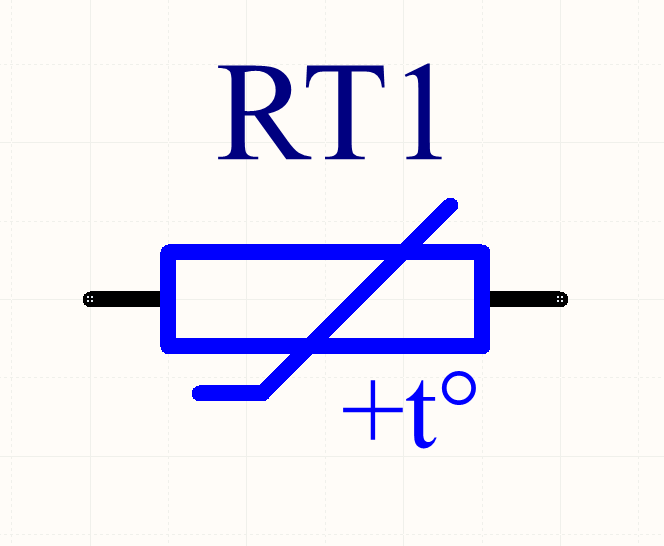
I use the designator prefix RT for thermistors (Resistance depends on Temperature), while using RV for varistors (Resistance depends on Voltage).
Important Parameters
Hold, Trip And Max Current
- Hold current: This is the maximum current the PTC can take without tripping.
- Trip current: This is the minimum current the PTC is guaranteed to trip at.
- Max current: This is the maximum current the PTC can withstand whilst in its tripped state without causing any damage.
When choosing a PTC, you want to make sure its hold current is above the current the load will draw under normal conditions.
Typically the trip current is around double the hold current (e.g. a hold current of 1A, and a trip current of 2A).
Rated Voltage
The rated voltage (a.k.a. maximum voltage, voltage (max), , ) is the maximum voltage the PTC can handle across its two pins without damage. This is usually applicable when the PTC is in its tripped state and the PTC is dropping almost the full supply voltage across it.
Time To Trip
The time to trip is the time the PTC fuse takes to transition from the normal to tripped state, when conducting a specific amount of current. The current that time to trip is provided at is usually a little higher than the trip current. The time to trip typically varies between 50ms to 5s. Generally, a fast time to trip is desirable.
Rmin/R1max
is the minimum resistance of the PTC in its initial (unsoldered) state. However, after a PTC trips and then is allowed to cool to reset, it does not usually fall back down to quickly, but can take days to reach this initial state. Instead, a (a.k.a. ) value is specified which is the resistance it returns to after some fixed time period, usually an hour. Note that soldering methods such as reflow soldering cause the same resistance change effect as tripping (after all, both processes heat it up!).
TIP: is useful for determining the peak fault current that will occur if a short-circuit occurs (before the PTC trips). . The rate at which this peak current will drop will depend on the time to trip.
The conditions to measure varies slightly between manufacturers. For example, LittelFuse specifies in its 60R series as:
Maximum resistance of device at 20°C measured one hour after tripping or reflow soldering of 260°C for 20 sec4.
You typically have to design the load so it can operate under normal conditions with a PTC whose resistance in somewhere between and .
Max. Power Dissipation
The maximum power dissipation (a.k.a. ) is the maximum power that the PTC can dissipate when in a tripped state under specified environmental conditions such as the ambient air temperature and PCB footprint (PCB footprint is more relevant for SMD devices than through-hole devices). Power dissipation above this limit can cause damage to the device due to overheating.
Types
Linear
Linear thermistors are those which have a roughly linear response in resistance to a temperature change. They are also known as silistors, as they are normally made with silicon.
Applications
PTC fuses can be used in a range of applications including:
- Overload protection on
VBUS(the positive voltage rail) on USB 2/3 ports. - Overload protection in DC motors.
- Preventing rechargeable batteries from overheating or overcharging (or discharging too fast).
PTC Thermistors vs. Fuses
When should a circuit designer use a PTC thermistor, and when should they use a fuse?
As already mentioned, a huge point of difference between a PTC thermistor and a fuse is the fact that a PTC thermistor is resettable, while a fuse is a blow once and replace component. This makes PTC thermistors suitable for applications where you might expect over-current conditions to occur frequently, and it would be inconvenient for the user to have to continually replace the fuse.
Conversely, this makes fuses better for applications where over-current conditions should not occur at all, and if they do, there is a higher chance of something being dangerous (e.g. live mains wiring that has shorted to the case). In these scenarios it can be safer to highlight the problem to the user and let the user/technician decide whether it is safe to replace the fuse and re-apply power.
Another advantage of PTC thermistors is cost in price-sensitive circuit board designs. As of the year 2016, a cheap SMD fuse in a chip package costs about US$0.40 in quantities of a 100, while a PTC thermistor for the same current rating in a similar SMD chip package costs about US$0.10, 4 times cheaper.
One consideration to make is that a PTC never reaches a complete open-circuit when it is tripped — it always lets a small current flow through the load. This is generally o.k. in most cases, but if you do need a proper open-circuit when a fault occurs, a fuse might be more suitable.
How To Calculate The Triggered Resistance
Most PTC thermistor datasheets will tell you the nominal off resistance (and/or its range of values), but not the triggered resistance! However, you can calculate this using the typical power value () that they provide.
is the typical power dissipated by the device when in a tripped state and in a fixed temperature (usually 23-25°C) still air environment. This is somewhat independent of the voltage applied to the thermistor, due to an increased voltage causing more heating, which in turn increases the resistance, which lowers the current and therefore the power dissipated. This is a form of negative feedback, and because this dissipated power is independent of the supply voltage, it can be specified as a property of the component on the datasheet.
To calculate the triggered resistance, use the following equation:
where:
is the triggered resistance of the PTC thermistor, in Ohms
is the voltage across the PTC thermistor (usually equal to the open-circuit supply voltage)
is the dissipated power of the PTC thermistor when in its triggered state, as given by its datasheet
The triggered resistance should be many orders of magnitude larger than the off resistance.
Manufacturers
- Eaton: Eaton sells a range of PTC fuses under the brand name Polytron.
- Bourns: They sell a family of resettable PTC fuses under the brand name Multifuse, with the part numbers beginning with MF-. See https://www.bourns.com/products/circuit-protection/resettable-fuses-multifuse-pptc.
- Bel:
- Littelfuse: Littelfuse sells PTCs under their brand name POLYFUSE4.
Supplier Links
PTC Reliability
The IEEE publication Failure Precursors for Polymer Resettable Fuses has some interesting reading on the behaviour of PTC fuses as they age and what the early indications are of failure.
Footnotes
-
ElectronicsPoint (2003). What is a positor? [forum post]. Retrieved 2022-07-13, from https://www.electronicspoint.com/forums/threads/what-is-a-positor.11721/. ↩
-
Roland (1984, Jul 31). JUNO-106: Service Notes (First Edition) [service notes]. Retrieved 2022-07-13, from http://www.analoguerenaissance.com/D80017A/juno-serv.pdf. ↩
-
DigiKey. Bel Fuse Inc. 0ZCJ0035FF2G [product page]. Retrieved 2021-12-14, from https://www.digikey.com/en/products/detail/bel-fuse-inc/0ZCJ0035FF2G/4156131. ↩
-
Littelfuse. POLYFUSE® Resettable PTCs: Radial Leaded > 60R Series [datasheet]. Retrieved 2021-12-14, from https://www.littelfuse.com/data/en/data_sheets/littelfuse_60r.pdf. ↩ ↩2