Mid-Chip Solder Balls

Mid-chip solder balls is a PCB manufacturing defect when 1 or more solder balls form between the two pads/leads of a SMD chip component during the soldering process. The ball is typically just off the side of the one of the pads.
What Causes Mid-Chip Solder Balls?
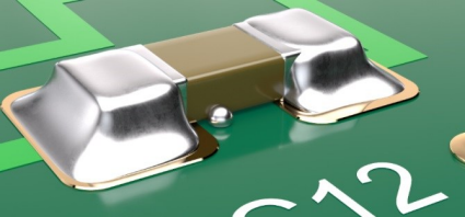
Mid-chip solder balls are usually caused by too much solder paste, poor hot slump, and/or insufficient wetting1. Solder paste is squeezed off the pad and underneath the chip, and does not coalesce back to the pad during reflow. Surface tension usually pulls the small amount of solder into a ball, which either remains hidden or protrudes from the sides of the chip, as shown in the image below:
Mid-chip solder balls are a problem as they can either create instant short circuits, or work free overtime (they normally only remain stuck to the PCB due to flux residue2), roll around and then cause short circuits at a later date.
Mid-chip solder balls commonly occurs on larger chip package sizes, from about size 0603 (imperial) and up3 2. There is dispute about which components are most effected, with some sources saying resistors cause the most mid-chip solder balls, due to only 3 surfaces at each end of the chip being wettable (top, bottom and end), whilst capacitors have 5(top, bottom, end and 2 sides)1. Others say capacitors are the biggest problem3.
Fixing Mid-Chip Solder Balls
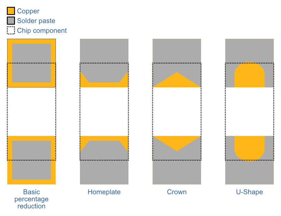
The most common remedy is to modify the solder paste opening on the stencil (called the aperture). The most basic change is a simple percentage reduction in the entire aperture on all sides. However, this sometimes is not the best solution, and more complex solder paste apertures are needed2.
There are few commons designs in use:
- Homeplate
- Crown
- U-Shape
Footnotes
-
Mark Currie, Neil Poole, Wanda O’Hara, Doug Dixon. Eliminating Mid-Chip Solder Balls: A Practical Guide to Understanding and Doing Away with this Common Defect. Retrieved 2023-06-19, from https://www.mouser.com/catalog/additional/Henkel_1enewsletter_1116_MidChipSolderBallPreventionfinal.pdf. ↩ ↩2 ↩3
-
Clive Ashmore (2018, Mar 21). Understanding and Eliminating Mid-Chip Solder Balls. Retrieved 2023-06-19, from https://circuitsassembly.com/ca/features-itemid-fix/408-screen-printing/29120-screen-printing-1804.html. ↩ ↩2 ↩3
-
Phil Zarrow, Jim Hall. Predicting Mid-Chip Solder Balling. Circuit Insight. Retrieved 2023-06-19, from https://www.circuitinsight.com/programs/55538.html. ↩ ↩2