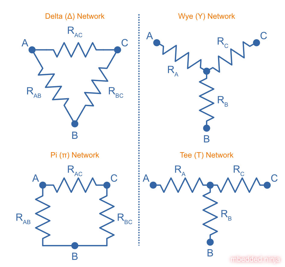
DELTA-WYE RESISTOR NETWORKS
Delta-Wye Resistor Networks
Date Published: | |
Last Modified: |
Overview
The following schematic shows the four common resistor network arrangements. Note that there is only two different connection topologies (those on the left, and those on the right), but there are two different ways of drawing each. The Delta network can be rearranged as the Pi network, and the Wye network rearranged as the Tee network.
With a few equations, you can transform a Delta network into a Wye network, and vise versa. These transformed networks are equivalent, i.e. from an outside observer who can only touch and measure the terminals \(A\)
, \(B\)
and \(C\)
, they wouldn’t be able to tell the difference. These transformations are useful for a number of reasons.
Delta To Wye Transformation
You can convert a Delta network of resistors to an equivalent Wye network with the following equations:
\begin{align} R_A = \frac{R_{AB}R_{AC}}{R_{AB} + R_{AC} + R_{BC}} \\ R_B = \frac{R_{AB}R_{BC}}{R_{AB} + R_{AC} + R_{BC}} \\ R_C = \frac{R_{AC}R_{BC}}{R_{AB} + R_{AC} + R_{BC}} \\ \end{align}
Wye To Delta Transformation
You can convert a Wye network of resistors to an equivalent Delta network with the following equations:
\begin{align} R_{AB} = \frac{R_A R_B + R_A R_C + R_B R_C}{R_C} \\ R_{AC} = \frac{R_A R_B + R_A R_C + R_B R_C}{R_B} \\ R_{BC} = \frac{R_A R_B + R_A R_C + R_B R_C}{R_A} \\ \end{align}
Resistor Network Example

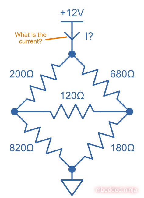
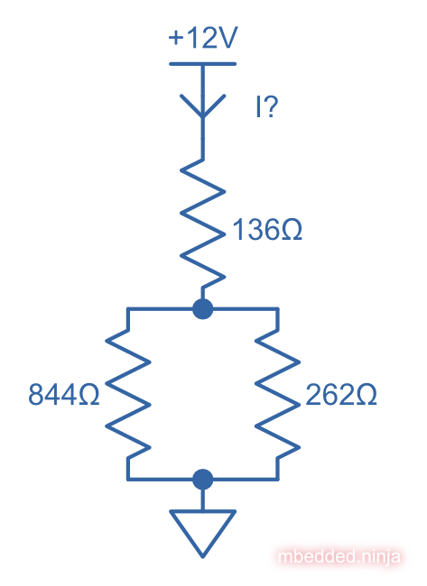
What is the current I drawn from the +12V for this resistor network? This can’t be solved purely with resistors-in-series and resistors-in-parallel equations, but can be done with the help of a Delta To Wye transformation.
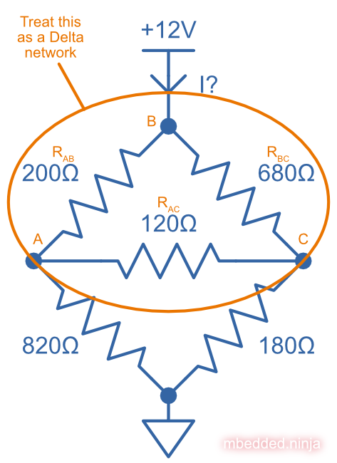
Let’s treat the top three resistors as a Delta network:
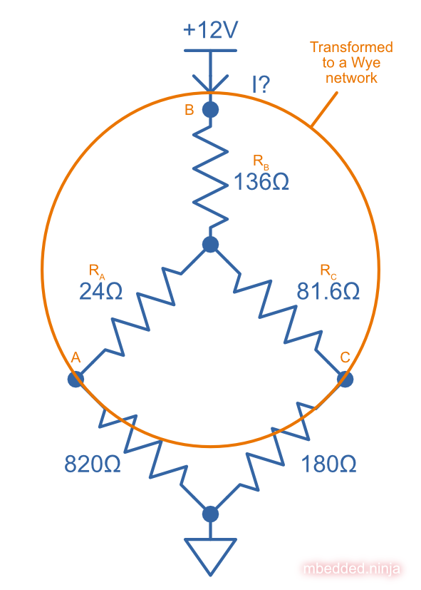
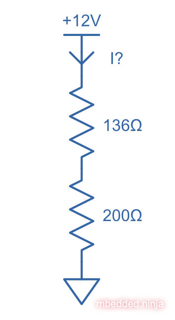
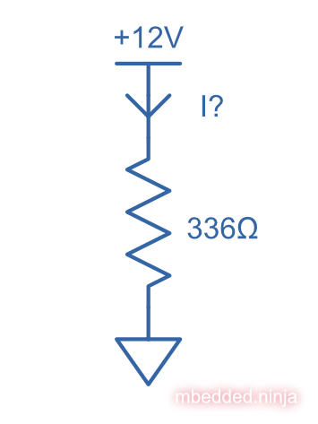
Let’s now convert this Delta network to a Wye network:
\begin{align} R_A &= \frac{R_{AB}R_{AC}}{R_{AB} + R_{AC} + R_{BC}} \nonumber \\ &= \frac{200\Omega \cdot 120\Omega}{200\Omega + 120\Omega + 680\Omega} \nonumber \\ &= 24.0\Omega \\ R_B &= \frac{R_{AB}R_{BC}}{R_{AB} + R_{AC} + R_{BC}} \nonumber \\ &= \frac{200\Omega \cdot 680\Omega}{200\Omega + 120\Omega + 680\Omega} \nonumber \\ &= 136\Omega \\ R_C &= \frac{R_{AC}R_{BC}}{R_{AB} + R_{AC} + R_{BC}} \nonumber \\ &= \frac{120\Omega \cdot 680\Omega}{200\Omega + 120\Omega + 680\Omega} \nonumber \\ &= 81.6\Omega \\ \end{align}
We can now collapse the rest of this circuit down by using the standard resistors-in-series and resistors-in-parallel simplifications:
\begin{align} R_{LL} &= 24\Omega + 820\Omega \nonumber \\ &= 844\Omega \\ R_{LR} &= 81.6\Omega + 180\Omega \nonumber \\ &= 262\Omega \\ \end{align}
We can now simplify the two bottom resistors which are in parallel:
\begin{align} R_{parallel} &= 844\Omega\ ||\ 262\Omega \nonumber \\ &= \frac{844\Omega \cdot 262\Omega}{844\Omega + 262\Omega} \nonumber \\ &= 200\Omega \\ \end{align}
And then we combine the last two resistors in series into just one resistor:
\begin{align} R_{single} &= 136\Omega + 200\Omega \nonumber \\ &= 336\Omega \\ \end{align}
Now it’s a simple task of \(I = \frac{V}{R} \)
:
\begin{align} I &= \frac{V}{R} \\ &= \frac{12V}{336\Omega} \\ &= 35.7mA \end{align}
Link to circuitjs simulation: https://tinyurl.com/y2tu5t2t
Authors

This work is licensed under a Creative Commons Attribution 4.0 International License .
Related Content:
- November 2014 Updates
- Two Bugs Which Need Fixing Soon...
- February-June 2014 Updates
- Calculators To Be Added!
- Altium Tricks And Standards