Programming Microcontrollers: An Overview

Interfaces
ARM DSTREAM?
JTAG
JTAG is a standard defining connections and protocols for testing/verifying PCBs and the devices on them. It is named after the Joint Test Action Group which defined the standard. It was formally codified in 1990 by IEEE in the standard IEEE 1149.1-19901. ICs supporting JTAG expose a Test Access Port (TAP) which the JTAG device connects to, allowing bi-directional serial data transfer. JTAG requires 4 signal lines (ignoring the rarely seen 2-signal variant).
Although JTAG was initially designed for board-level testing and verification to address common soldering faults in the 1980’s, it has evolved and is now most commonly used today as an in-circuit programming/debug protocol for microcontrollers, microprocessors, FPGAs, and other similar programmable ICs.
JTAG allows the following:
- Processing halting
- Single-stepping
- Writing to non-volatile memory (programming)
| Name | I/O (w.r.t. programmer) | Description |
|---|---|---|
| TCK | Output | The Test Clock pin is driven by the programmer and provides a clock for the data on the other pins. |
| TDI | Output | The Test Data In pin is driven by the programmer and provides serial data to the target during programming/debugging. |
| TDO | Input | The Test Data Output pin is driven by the target device and provides serial data to the programmer during programming/debugging. |
| TMS | Output | The Test Mode Select pin is used to set the state of the Test Access Port controller. |
| nTRST | Output | The “Tap Reset” pin is driven active low to reset the target device. Typically pulled high on the target board. Sometimes just called TRST, although always active low. |
A 2-wire (excluding GND) “reduced pin count JTAG” is specified in IEEE 1149.71. The two wires that are used are TMSC (test serial data) and TCKC (test clock). This 2-wire variant is not common.
CoreSight is a collection of technologies to allow for the debugging of ARM based SoCs. It includes systems built on JTAG for debugging.
RTCK (return clock) is a signal created to use be able to use synchronized TAP controllers in ARM9 and ARM11 cores. It is an output of the target system back to the JTAG adapter and is used for synchronization purposes. The RTCK is usually driven by the last flip-flop in the synchronization chain on the target device. The adapter will not change TCK until it gets back a signal on RTCK, this process is called adaptive clocking2.
SWD
SWD (Single Wire Debug) is a two-wire programming/debugging interface for programmable ICs such as microcontrollers. It is a popular alternative to JTAG. It is formally specified in the ARM Debug Interface v5.
| Name | I/O (w.r.t. programmer) | Description |
|---|---|---|
| SWDCLK | Output | Clock output to target device. Frequency selection is up to the host to decide, up to about 60MHz in practice.3 |
| SWDIO | Bi-directional | Synchronous bi-directional data. |
Whilst officially just a 2-wire interface, it is commonly bundled with 1-2 other signals.
| Name | I/O (w.r.t. programmer) | Description |
|---|---|---|
| VTREG | Input | Target voltage so the adapter knows what counts as a logical 1 and 0 on the other wires. |
| SWO | Input | Serial Wire Output. Single-wire trace output from the target, used by the Serial Wire Viewer (SWV). |
| nRST | Output | Used to reset the target device. Active low logic. |
SWDCLK, SWDIO and SWO should be pulled high by approx. so that they remain in a stable state when not driven4.
SWD uses a bus called DAP (Debug Access Port). On this bus there is one master, the DP (Debug Port, typically a USB dongle when programming microcontrollers), and one or more slaves called APs (Access Ports). There are three different Debug Ports3:
- JTAG Debug Port (JTAG-DP): Uses the standard JTAG interface.
- Serial Wire Debug Port (SW-DP): Uses the SWD protocol.
- Serial Wire / JTAG Debug Port (SWJ-DP): A combination of the previous two, this port can either use SWD or JTAG to access the DAP bus. The
TCKandTMSJTAG signals are re-used for the SWDSWCLKandSWDIOsignals.
ARM specifies the following two Access Ports:
- Memory Access Port (MEM-AP): Provides access to core memory and registers.
- JTAG Access Port (JTAG-AP): Provides access to a JTAG chain from the DAP.
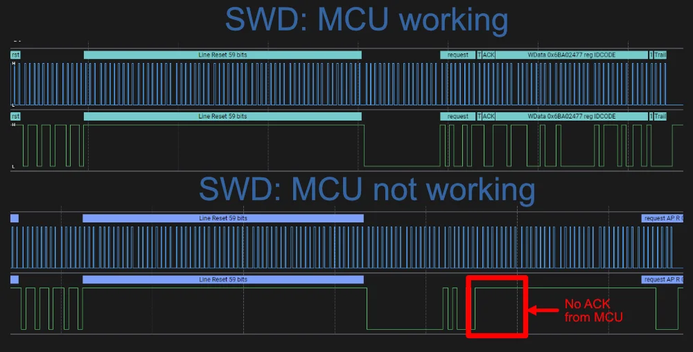
SWD communication begins with a line reset, where the DP generates 50+ clock cycles on SWDCLK while driving SWDIO high (as shown in the figure below). This gets the AP state machine into a known state for further communication.
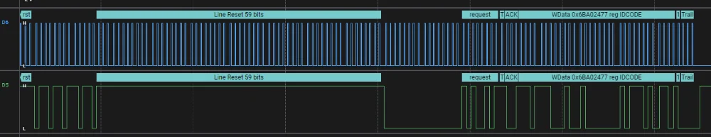
SWDCLK which drives SWDIO high. The IDCODE is the next 32 bits on SWDIO.If a MCU is not working for some reason (not connected properly, dead, etc.), your first sign of failure will usually be when it fails to ACK the IDCODE request from the DP. The figure below shows a comparison of a working MCU (top) and a not working MCU (bottom) during a line reset and IDCODE request. The working MCU ACKs the IDCODE request from the DP, while the not working MCU does not.
SWV
Serial Wire Viewer (SWV) is the protocol used by the SWO pin on the SWD connector5. It is only available for ARM Cortex-M3 cores and higher, it is NOT available on Cortex M0 or M0+ cores.
32 available ITM stimulus ports. ARM recommends5:
- Port 0 is used for text data (e.g. data from
printf()) - Port 31 is used for RTOS event data
- All other channels are up to the user to decide.
SWV can give you printf() style debugging output, in where the printf() function calls the CMSIS ITM_SendChar() function.
ETM
4-bit.
Semihosting
Semihosting is an ARM feature which allows an ARM-based target to communicate with and use the input/output (IO) facilities on the host computer which is running a debugger6. Semihosting is commonly used to send printf() calls on the target to the host, and be displayed whilst debugging through a terminal on the host.
NOTE: ARM processors prior to ARMv7 use the SVC instructions, formerly known as SWI instructions, to make semihosting calls. However, if you are compiling for an ARMv6-M or ARMv7-M, for example a Cortex-M1 or Cortex-M3 processor, semihosting is implemented using the BKPT instruction6.
Segger Real-Time Terminal (RTT)
The Segger Real-Time Terminal (RTT) provides a bi-directional data transfer mechanism between a host and target microcontroller. RTT emulates a telnet connection on the host machine7. For example, to connect to Channel 0 (designed for terminal use), you connect via a Telnet client to localhost:19021.
It is currently supported by the following cores8:
- ARM Cortex-M0/M0+/M1/M3/M4/M7/M23/M33
- Renesas RX100/200/600
Example target-side code to send a message to the host via Segger RTT on Channel 08:
int main(void) { do { SEGGER_RTT_WriteString(0, "Hello World from SEGGER!\r\n"); _Delay(100); } while (1); return 0;}TagConnect
Segger has jumped on the bandwagon and provides a “J-Link 6-pin Needle Adapter” which looks like a re-branded TagConnect to mate with their J-Link programmer.
Cortex Debug Connector Pinouts
There are industry-standard connector sizes and pinouts for debugging the Cortex range of ARM-based microcontrollers (e.g. microcontrollers with a Cortex-M0, Cortex-M0+, Cortex-M3, etc.).
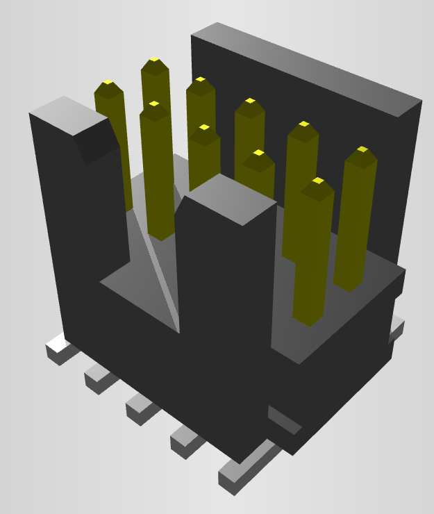
10-pin, 1.27mm Pitch
The 10-pin, 2x5, 1.27mm pitch (0.050”) connector is the most common debug connector used with Cortex-based microcontrollers.

The official connector is the Samtec FTSH-105-01, yet luckily these header-style connectors are standardized across manufacturers and almost any 1.27mm 2x5 header-style connector will work.
Sometimes Pin 7 is removed from the male header, and the female header has a blank position in the same location (i.e. no receptacle). This is to “key” the header so it can’t be mated incorrectly. Another way of preventing incorrect mating is to use a keyed shroud.
Pin 9 (GND) can also be used for detection.
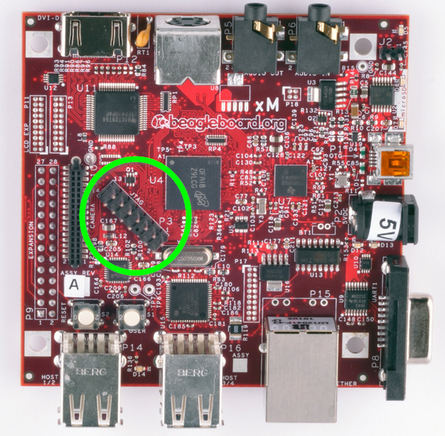
14-pin TI Connector

The EMU0 and EMU1 pins can be used for cross-core triggering (e.g. one core halts and signals the other cores to halt)12. They are not supported by ARM DSTREAM13.
The BeagleBoard Rev D and Beagleboard-xM use this connector.
20-pin ARM “Standard” Debug Connector Pinout
This is the most common 20-pin debug connector pinout for an ARM device.

NOTE: Pin 2 may be specified as either VCC (optional) or NC (not connected). In most situations I’ve seen this as NC.
20-pin Cortex Debug + ETM Connector Pinout

Supported by the ULINKPro.
38-pin MICTOR Connector
Connecting a trace probe to a ARM target.
Footnotes
-
Wikipedia (2004, May 6). JTAG [wiki]. Retrieved 2021-11-08, from https://en.wikipedia.org/wiki/JTAG. ↩ ↩2
-
ARM. DSTREAM-XT System and Interface Design Reference Guide: RTCK. Retrieved 2021-11-08, from https://developer.arm.com/documentation/102444/1-0/Debug-and-trace-interface/RTCK. ↩
-
Nicolas Oberli (2019, May 16). SWD – ARM’s Alternative To JTAG. Kudelski Security Research. Retrieved 2021-11-08, from https://research.kudelskisecurity.com/2019/05/16/swd-arms-alternative-to-jtag/. ↩ ↩2
-
ARM. DSTREAM-XT System and Interface Design Reference Guide: SWD Connections. Retrieved 2021-11-09, from https://developer.arm.com/documentation/dui0499/d/ARM-DSTREAM-Target-Interface-Connections/SWD-connections. ↩
-
Code Inside Out (2021, Nov 11). Serial Wire Viewer (SWD + SWO). Retrieved 2021-11-12, from https://www.codeinsideout.com/blog/stm32/swv/. ↩ ↩2
-
ARM Developer. What is semihosting?. Retrieved 2021-11-12, from https://developer.arm.com/documentation/dui0471/g/Bgbjjgij. ↩ ↩2
-
Erich Styger (2015, Jul 7). Using Segger Real Time Terminal (RTT) with Eclipse. MCU on Eclipse. Retrieved 2021-11-12, from https://mcuoneclipse.com/2015/07/07/using-segger-real-time-terminal-rtt-with-eclipse/. ↩
-
Segger. About Real Time Transfer. Retrieved 2021-11-13, from https://www.segger.com/products/debug-probes/j-link/technology/about-real-time-transfer/. ↩ ↩2
-
Keil. CoreSight Connectors. Retrieved 2021-11-05, from https://www2.keil.com/coresight/coresight-connectors. ↩ ↩2 ↩3
-
Samtec. FTSH-105-01-L-DV-K High Reliability Header Strips, 0.050” pitch. Retrieved 2021-11-05, from https://www.samtec.com/products/ftsh-105-01-l-dv-k. ↩
-
Segger. 14-Pin TI Adapter. Retrieved 2021-11-07, from https://www.segger.com/products/debug-probes/j-link/accessories/adapters/14-pin-ti-adapter/. ↩
-
Texas Instruments. JTAG Connectors and Pinout. Retrieved 2021-11-07, from http://software-dl.ti.com/ccs/esd/documents/xdsdebugprobes/emu_jtag_connectors.html. ↩ ↩2
-
ARM. ARM DSTREAM System and Interface Design Reference: TI JTAG 14. Retrieved 2021-11-07, from https://developer.arm.com/documentation/dui0499/d/ARM-DSTREAM-Target-Interface-Connections/TI-JTAG-14. ↩
-
Beagleboard (2017, May 4). BeagleBoard-xM. Retrieved 2021-11-07, from https://beagleboard.org/beagleboard-xm. ↩