

 NinjaCalc
Thermoelectric Effect

Seebeck Effect
The Seebeck Effect is the electro-motive force (EMF, can be thought of as a voltage) which appears across two points of an electrically conductive material when there is a temperature difference between them. The amount of EMF depends on the material used.
The following diagram shows the basic environment to create the Seebeck Effect.
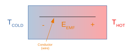
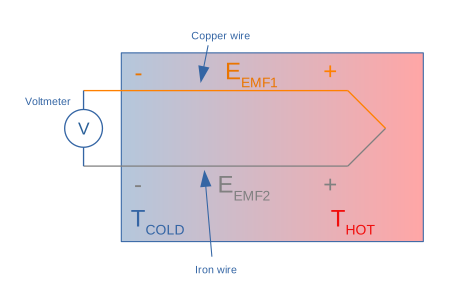
Note that in practice, the EMF generated across a single conductor moving through a temperature gradient is not really useful for anything, since to measure this voltage and/or conduct any current, you need a return path. However, if you used the same material wire for the return path, it would experience the exact same temperature gradient but in reverse, the two EMFs would cancel each other out, and you would measure no voltage across the loop. This is where a second trick is used to generate a working thermocouple --- a second wire of different material is used for the second half of the loop. The different material ideally has a widely different Seebeck coefficient and hence generates a different EMF for the same temperature differential, thus creating a measurable voltage and/or current.
Don’t think you can cheat by measuring the voltage across a single wire with a multimeter…the second temperature gradient will still be there, in the wires of the multimeter. The following diagram shows a practical thermocouple design using dissimilar conductors to form a complete circuit:
The Seebeck Effect is primarily used to make thermocouple based temperature sensors and thermoelectric power generators (fun fact: the power source aboard the Mars rover Perseverance uses the Seebeck Effect, it uses radioactive decay to create the required temperature differential to then generate electric power). The reverse effect, where an applied voltage produces a temperature difference, is the Peltier effect.
The Seebeck Coefficient
The Seebeck coefficient is calculated from the following equation:
where:
is the Seebeck coefficient, in
is the change in voltage, in
is the change in temperature, in (although would also work)
Because of the negative sign in the above equation, a positive Seebeck coefficient will result in the higher temperature region having a lower voltage. Most Seebeck coefficients are small relative to and are written in units of .
Semiconductors also have Seebeck coefficients. In general, P-doped semiconductors have positive Seebeck coefficients and N-doped semiconductors have negative Seebeck coefficients. Most semiconductor Seebeck coefficients are much larger than those of metals. In an intrinsic semiconductor the electron and hole contributions oppose each other, so the net Seebeck coefficient tends towards zero (and is exactly zero only when they perfectly cancel).
The Seebeck coefficient of some common metals and semiconductors, relative to Platinum, are shown in the below tables1:
Metals
| Material | Seebeck Coefficient () |
|---|---|
| Copper | 6.5 |
| Gold | 6.5 |
| Lead | 4.0 |
| Aluminium | 3.5 |
| Platinum | 0 (by definition) |
| Sodium | -2.0 |
| Nickel | -15 |
| Constantan | -35 |
| Bismuth | -72 |
Semiconductors
Notice how the coefficients are typically much higher than metals!
| Material | Seebeck Coefficient () |
|---|---|
| Se | 900 |
| Te | 500 |
| Si | 440 |
| Ge | 300 |
| PbTe | -180 |
| -1990 |
Footnotes
-
Electronics Cooling (2006, Nov 1). The Seebeck Coefficient [article]. Retrieved 2021-03-16, from https://www.electronics-cooling.com/2006/11/the-seebeck-coefficient/. ↩