

 NinjaCalc
Timers And Multivibrators

Multivibrators are 2-state electronic circuits used to make simple waveforms, oscillators and timers.
There are three main types of multivibrator:
- Astable multivibrator: A circuit which is not stable (hence astable) in any state, it continuously switches from one state to the other.
- Monostable multivibrator: One state is stable, while the other is not. A trigger input puts this circuit into the unstable state, and at some time after this, the circuit will automatically switch back to the stable state. This is also called a one shot.
- Bistable multivibrator: The circuit is stable in both states. A trigger input is needed to switch from one state to the other. This circuit is much more commonly known as a flip-flop.
History
The first recorded multivibrator was the Abraham-Bloch oscillator in 1919, which functioned as an astable multivibrator. The circuit was called a multivibrator because the square wave output contained a large proportion of harmonics.1 Instead of being unwanted, these harmonics were actually useful in the calibration of RF devices.
Basic BJT Astable Multivibrator
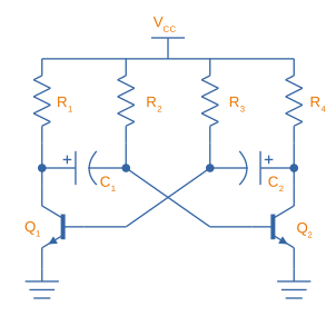
A basic astable multivibrator can be made from two BJT NPN transistors and a handful of passive components, as shown below:
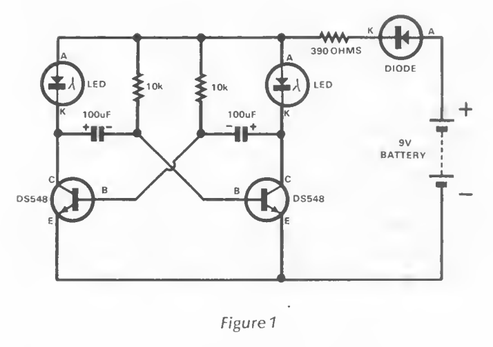
As a throwback to the past, Dick Smith’s Fun Way Into Electronics (first printed in 1979) contains a “flasher” which is exactly this circuit. This book is arguably what sparked my interest in Electronics!
How It Works
TODO: Add content here.
The 555 Timer IC
Due to its popularity, the 555 timer is sometimes referred to as the “IC Time Machine”.2
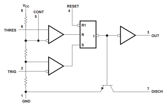
Internal Workings
Modes Of Operation
Monostable Mode (Time Delay Mode)
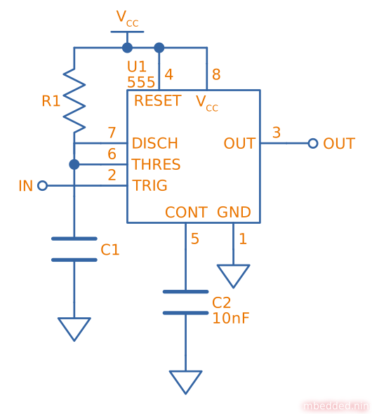
Monostable mode is when the 555 timer is configured to output a single pulse after a fixed amount of time. It only outputs one pulse and then stops until it is externally reset. This mode is used for creating a time delay. The schematic below shows a basic monostable 555 circuit.
Astable Mode
Astable mode is when the 555 timer is configured to output a continuous waveform with a fixed frequency and duty cycle. It is similar to monostable mode, except that it continually resets itself after every pulse.
Astable mode is also called running the 555 timer as a multivibrator. The duty cycle of the output waveform cannot be reduced below 50%. If you want a duty cycle lower than that, you have to use an inverter on the output.
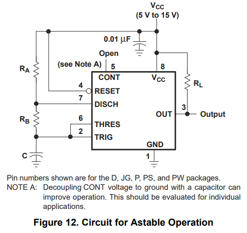
Equations (where and are labelled and respectively in the schematic above):
Astable 555 Timer Calculator
Use the calculator below to find the two timing resistors (, ) and the on/off times needed to run a 555 in astable mode at a given output frequency, duty cycle and timing capacitor. The duty cycle must be greater than 50% — to get a lower duty cycle, run an inverter on the output.
Footnotes
-
Abraham, H.; Bloch, E. (1919). Mesure en valeur absolue des périodes des oscillations électriques de haute fréquence [journal article]. Annales de Physique. Retrieved 2026-07-04, from https://doi.org/10.1051/anphys/191909120237. ↩
-
Maniktala, Sanjaya (2012). Voltage-Mode, Current-Mode (and Hysteretic Control) [technical article]. Microsemi. Retrieved 2021-08-22, from https://www.microsemi.com/document-portal/doc_view/124786-voltage-mode-current-mode-and-hysteretic-control. ↩