Wheatstone Bridges

The Wheatstone bridge (a.k.a. resistance bridge) is a circuit consisting of four resistive components. It has the benefit of being able to perform accurate measurements of resistance. The below image shows the basic schematic:
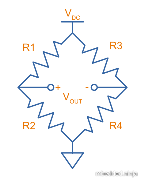
Below is the general equation for the Wheatstone bridge:
The output voltage (and consequentially, output current) is 0 when both of the “legs” of the bridge are balanced. That is:
The traditional use is to replace the bottom resistors on both legs of the Wheatstone bridge — one leg with a variable resistor (rheostat or potentiometer) and the other with an unknown resistance which you want to measure. The variable resistor is adjusted until the output voltage (or current) is . Assuming you know the resistance of the rheostat, you can calculate the resistance of .
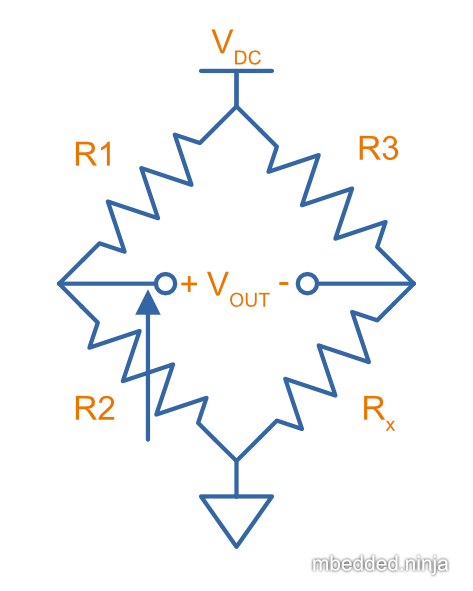
In the scenario shown above, the unknown resistance can be found with:
Benefits Over A Simple Resistor Divider
You might be wondering why use a complicated 4-resistor Wheatstone bridge when you could just use a simple 2-resistor resistor divider, and measure the output voltage. By knowing the output voltage, the supply voltage, and at least one of the resistances, you can then calculate the other resistance in a resistor divider. The benefit of a Wheatstone bridge is that it is inherently a differential measurement, rather than a single-ended one (which a resistor divider is). This means:
- You don’t need a precise auxiliary voltage reference to compare with if you just plan on balancing the bridge (i.e. making ). Because it is ratiometric, in this case the supply voltage to the bridge is also unimportant.
- Even if you are measuring the output voltage (and hence need an auxiliary voltage reference): ** Environmental effects that effect both legs of the bridge cancel each other out (e.g. temperature-related drift in the resistances) ** The common-mode voltage that a single-ended resistor divider gives you has been removed, hence it is much easier to apply a large gain to a differential Wheatstone output to measure small voltages.
History
The Wheatstone bridge was invented by Samuel Hunter Christie in 1833, but got it’s name from Sir Charles Wheatstone, who improved and popularized the circuit in 18431.
Applications
- Strain gauge measurement: Metal foil strain gauges change their resistance depending on the strain they are subject to. Measuring the small change in resistance precisely is normally done with a Wheatstone bridge circuit. In this application the bridge is not balanced, but rather the output voltage is then fed into an amplifier and then measured (usually with an ADC).
- Weight-scales: This is typically done with four load cells (each being a strain gauge), where the four load cells are arranged into a Wheatstone bridge topology.
- Temperature measurement: One way of measuring temperature is with a thermistor, a component which changes resistance with temperature.
Footnotes
-
National MagLab (2014, Dec 10). Wheatstone Bridge – 1843. Retrieved 2022-01-17, from https://nationalmaglab.org/education/magnet-academy/history-of-electricity-magnetism/museum/wheatstone-bridge-1843. ↩