STM32 Microcontrollers

STM32 is a family of 32-bit, ARM Cortex-M microcontrollers manufactured by ST Microelectronics.
All STM32 micros are supported by ST’s own STM32CubeIDE.
Development Kits
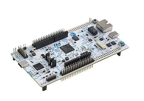
A very popular range of development kits using the STM32 microcontrollers is the STM32 NUCLEO. These boards feature a STM32 microcontroller, integrated programmer with UART, and both Arduino and Morpho-style header pins (Morpho is ST’s proprietary header arrangement which provides greater connectivity than the industry-standard Arduino arrangement).
A Windows machine is required to update the firmware on the Nucleo programmer/debugger IC (the IC which emulates an ST-Link).
Programmers
To get an in-depth overview of all the ST programmers by ST themselves, see https://www.st.com/resource/en/technical_note/dm00290229-overview-of-stlink-derivatives-stmicroelectronics.pdf.
ST-LINK/V1
ST-LINK/V1 is deprecated.
ST-LINK/V2
The ST-LINK/V2 is an in-circuit programmer and debugger for the STM8 and STM32 families of microcontrollers. It supports the SWIM (Single Wire Interface Module, for STM8 only)1, SWD (Single Wire Debug) and JTAG programming protocols.
ST-LINK/V2-ISOL
The ST-LINK/V2-ISOL is similar in functionality to the ST-LINK/V2 but with additional isolation between the PC and target board.
STLINK-V3
Designed to supersede the ST-LINK/V2 family of programmers. Comes in three flavours:
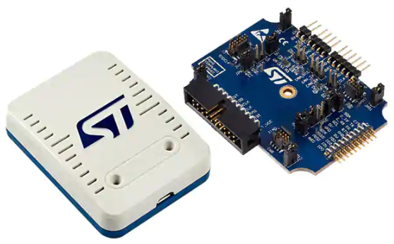
- STLINK-V3SET: The “standard” programmer that comes with an enclosure. The main module board is the MB1441. Optional adapter boards can be attached to it for extra functionality2.
- STLINK-V3MINI: A miniature form of the programming, that comes as a bare PCB. Much cheaper than the STLINK-V3SET.
- STLINK-V3MODS: A programmer on a castellated-edged PCB module, designed to be soldered onto a PCB containing the microcontroller to be programmed.
All have 1 or more virtual comm ports (VCPs) and mass-storage device emulation for drag-and-drop flash programming.
STDC14 Connector
The STDC14 pinout/connector was introduced in STLINK-V3. This is a 14-pin 2x7 1.27mm pitch header-style connector. The middle 10-pins copy the standard 10-pin ARM Cortex programming connector. 2 on one end add UART TX/RX, and the other two on the other end are reserved.
The pinout for the STDC14 connector is shown the below table2:
| Pin No. | Description | Pin No. | Description |
|---|---|---|---|
| 1 | Reserved | 2 | Reserved |
| 3 | T_VCC | 4 | T_JTMS/T_SWDIO |
| 5 | GND | 6 | T_JCLK/T_SWCLK |
| 7 | GND | 8 | T_JTDO/T_SWO |
| 9 | T_JRCLK/NC | 10 | T_JTDI/NC |
| 11 | GNDDetect | 12 | T_NRST |
| 13 | T_VCP_RX | 14 | T_VCP_TX |
The TagConnect TC2070-IDC-050 or TC2070-IDC-NL-050 cables can be used with the STLINK-V3 and it’s STDC14 connector to provide connector-less pogo-pin style programming3.
NUCLEO Development Kits
Given the costlier nature of the ST-LINK compared to the NUCLEO development kits, it makes economic sense just to by the NUCLEO development kits and use them as standalone programmers (the kits provide header pins which breakout the programming pins, so you can route it to an off-board micro). You also get the added benefit of having a extremely useful built-in UART (which emulates a COM port when the on-board programmer is plugged into a computer via USB cable), which for example, can be used as a debug UART. The standard programmers don’t have this!
STM32F0
The STM32F0 is a family of “general purpose” STM32 microcontrollers. The family uses a 48MHz ARM Cortex-M0 CPU architecture.
Low-power modes:
- Sleep mode: Only the CPU is stopped. All peripherals continue to operate and can wake-up the CPU.
- Stop mode: A mode designed to put everything into a low-power state but retain the content of SRAM and the registers.
- Standby mode: The lowest-power mode. Everything is stopped and SRAM/register content is lost, except for the registers in the RTC domain and standby circuitry
GPIO capabilities:
GPIO can be configured as one of the following outputs:
- Push-pull
- Open-drain
Or as the following inputs:
- High-impedance
- Pull-up
- Pull-down
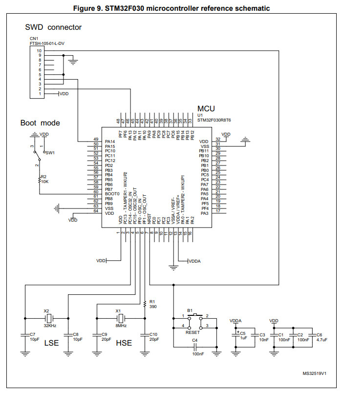
Reference schematic for the STM32F030 (just power, clock and programming):
STM32F1
The STM32F1 is a family of “general purpose” STM32 microcontrollers. The family uses a ARM Cortex-M3 CPU architecture.
Some things to note:
- All GPIO pins with the same integer last digit across each port (e.g.
PA1,PB1,PC1, …) are connected to the same interrupt, and only one pin may be connected to the interrupt at any one time. Be careful when routing signals to your GPIO pins! - Peripherals are divided into two APB buses. All peripherals connected to
APB1run at half the main clock frequency, and peripherals connected toAPB2run at the main clock frequency.
To develop with STM32F1 microcontrollers you will need two PDFs, the specific “datasheet” for the exact microcontroller you are using, and the more general and much bigger reference manual.
STM32G
The STM32G is a family of “general purpose” STM32 microcontrollers. The family either uses a 64MHz ARM Cortex-M0+ CPU architecture (the M0+ instructions are an optimized superset of the M0, the M0+ also has a two-stage pipeline, while the M0 has a three-stage pipeline) for the G0 or the Cortex-M4F for the G44.
STM32G0
- STM32G0x0: Value line. Cheapest STM32G0 microcontrollers, with an entry-level set of analogue peripherals.
- STM32G0x1: More analogue features than the STM32G0x0.
STM32G4
Family of mixed-signal microcontrollers, which include both DSP and FPU instructions. This family uses the ARM Cortex-M4F CPU architecture. This is further sub-divided into the following sub-families:
- STM32G4x1: Access line: General-purpose microcontrollers with entry-level set of analogue peripherals.
- STM32G4x3: Performance line: General-purpose microcontrollers with the maximum number of analogue peripherals.
- STM32G4x4: Hi-resolution line: Features a high-resolution timer and complex waveform builder plus event handler for digital power conversion.
STM32N6
STM32N6 is a series of STM32 MCUs with dedicated hardware for running edge AI. They feature an Arm Cortex-M55 running at 800 MHz and a NPU (neural processing unit) running at 1 GHz and capable of 0.6 TOPS (tera operations per second). The NPU is the ST Neural-ART accelerator.5
The STM32N6 directly supports image processing pipelines with a built-in MIPI CSI-2 interface and H264 hardware encoder.5 It has a hexa-SPI and FMC bus for fast communication with external memory.
The STM32N6 is further sub-divided into the following “lines”:
- STM32N6x7: AI line: Has a NPU (Neural-ART Accelerator). This is labelled “with AI acceleration”.
- STM32N6x5: General purpose line: Does not have a NPU.
Within these two lines some have HW cryptography units while others do not.
There are two primary development kits for the STM32N6. The comprehensive STM32N6570-DK contains a camera, LCD screen and touch panel, USB, Ethernet, microphone and 1 Gbit SPI flash memory. It features the STM32N657X0H3Q MCU.
The other dev kit is the NUCLEO-N657X0-Q which is structured like STs other Nucleo dev. kits. It contains the STM32N657X0 MCU and provides a great way to test out the STM32N6 series of MCUs. It includes features such as: user buttons and LEDs, Ethernet, MIPI20 connector, M.2 key A serial memory connector and a CAN FD header.6 Unlike STM32N6570-DK, it does not come with a camera and LCD touch screen.
STM32WLEx
The STM32WLEx is a family of “SoC” microcontrollers featuring a STM32L4 coupled with a wireless radio IC that supports LoRaWAN (both of these are in the same physical IC).
Footnotes
-
ST Microelectronics (2016, Aug). UM0470 User manual: STM8 SWIM communication protocol and debug module. Retrieved 2020-09-03, from https://www.st.com/resource/en/user_manual/cd00173911-stm8-swim-communication-protocol-and-debug-module-stmicroelectronics.pdf. ↩
-
ST Microelectronics (2021, Dec). UM2448 User manual: STLINK-V3SET debugger/programmer for STM8 and STM32. Retrieved 2022-08-09, from https://www.st.com/en/development-tools/stlink-v3set.html#documentation. ↩ ↩2
-
TagConnect. Tag-Connect Solutions for Debuggers & Programmers: ST-Link-V3 Cable Selection. Retrieved 2022-08-09, from https://www.tag-connect.com/debugger-cable-selection-installation-instructions/stlink-v3. ↩
-
Wikipedia (last edited 2021, Aug 31). STM32. Retrieved 2022-01-12, from https://en.wikipedia.org/wiki/STM32. ↩
-
STMicroelectronics. STM32N6 Series [product page]. Retrieved 2026-06-09, from https://www.st.com/en/microcontrollers-microprocessors/stm32n6-series.html. ↩ ↩2
-
STMicroelectronics. NUCLEO-N657X0-Q - STM32 Nucleo-144 development board with STM32N657X0 MCU, SMPS, supports Arduino, and ST morpho connectivity [product page]. Retrieved 2026-06-09, from https://www.st.com/en/evaluation-tools/nucleo-n657x0-q.html. ↩ ↩2