Current Mirrors

A current mirror is a circuit designed to “copy” (mirror) the current through one part of a circuit into another. The output current is kept relatively constant even though the load resistance may be dynamically changing.
Current mirrors are used extensively inside analogue ICs such as operation amplifiers (op-amps).
Basic BJT Current Mirror
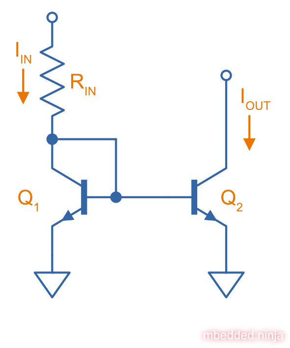
You can make a basic current mirror from nothing but two bi-polar transistors (BJTs). Shown below is a basic BJT current mirror made from two NPN BJTs:
How Does It Work?
Both and should be identical transistors at the same temperature. The clever trick in this circuit is the base of which is connected to its collector. The BJT will adjust it’s base-emitter voltage to pass the input current. This is then applied to the base of . Because it is the same type of transistor as , this should cause the same base current, and the same will produce the same collector current through .
Below is a circuit simulation of this basic BJT current mirror. 4.37mA is provided to the input leg of the current mirror, and the current mirror sinks 4.28mA from the output. Close enough for many applications!
The main current error in the basic BJT current mirror circuit is because the base of Q1 and Q2 “suck” away some of the current you are tying to measure through the collector of Q1. If Q1/Q2 had current gains of 100, then of the current will be diverted into the bases rather than through the collector, and hence not mirrored on the output.
Buffered Feedback Current Mirror
As mentioned above, one of the main problems with the basic current mirror is that the bases of Q1 and Q2 “suck” away some of the input current. To improve on this, we can add another NPN BJT on the input side to “buffer” the base of Q1/Q2. Now only of the current is diverted away. This is called the buffered feedback current mirror, or emitter follower augmented mirror1.
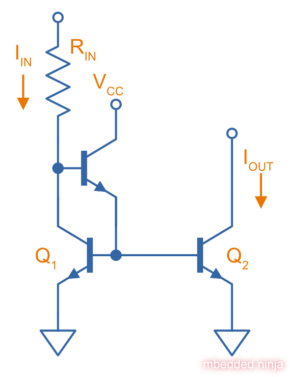
Below is a simulation of the buffered feedback current mirror. Notice now the the output current is only different from the input! This is a great improvement on the error of the basic BJT current mirror!
Footnotes
-
Analog Devices (2021, Sep 17). Chapter 11: The Current Mirror. Retrieved 2022-08-06, from https://wiki.analog.com/university/courses/electronics/text/chapter-11. ↩