Schematic Tips And Tricks
Make Input Connectors Face Right, Output’s Face Left
This makes your design easier to follow. Things come in on the left, and leave on the right. Most EDA software allows you to flip (a.k.a mirror) schematic symbols (in Altium, press x while dragging the schematic symbol).
Of course, there are problems with such a general rule. What defines an input or an output in the first place? What do you do if the connector has both inputs and outputs?
The answer, use common sense. Things like temperature sensors, they can probably be considered inputs. Things like connections to a motor, they can probably be considered as outputs (even though any feedback pins are inputs).
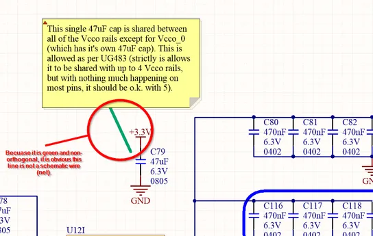
Schematic Notes
Make sure all note arrows cannot be confused with schematic wires/nets. I make sure of this by changing the colour of the arrow, and by always making it non-orthogonal (i.e. on a slant).


