Current Sensing
Low-Side Resistive Current Sensing
One of the most basic ways to measure current is to use a low-side current sensing resistor. Benefits of this method are:
- Simple and cheap
- Single-ended output due to resistor being on the low-side. This means you can fed a single signal into a ADC (because it is referenced to GND).
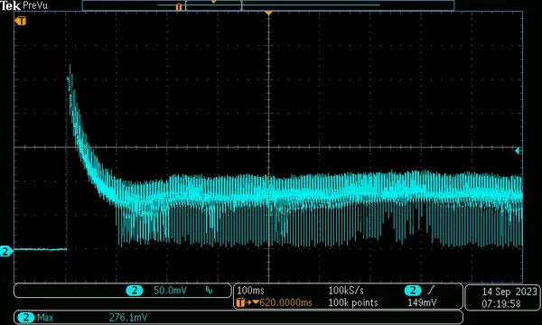
The below image shows the oscilloscope the voltage on the top-side of a low-side 100mΩ resistor connected to a small brushed DC motor as it is turned on. The voltage peaks at 280mV, which corresponds to 2.8A (). It then drops and settles down to approx. 90mV, which corresponds to 0.9A. I think the noise is due to the switching action of the motors brushes.

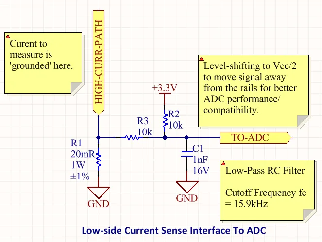
The following image shows a schematic for a low-side current sensing circuit that can be connected to an ADC. This can be used for applications such as brushed/BLDC motor phase current measurement (see the BLDC Motor Control page). It uses a current sense resistor on the low side of the current path (i.e., next to ground) and then shifts the result away from the rails to for better precision/compatibility with ADCs.

The value of the resistance is a trade-off between resolution and power dissipation/circuit disruption. The higher the current-sense resistance, the large the voltage signal for a given current and hence better resolution. However, a larger voltage means both more power dissipation in the resistance AND greater disruption to the circuit you are trying to measure. Assuming a resistive load, disruption means the load begins to see a reduced voltage and draws less current (the very current you are trying to measure!).
Generally speaking, choosing a resistance that drops a few hundred of millivolts at max. current is a good starting point. This voltage can be fed directly into a MCU ADC if you just want a rough current measurement, or can be pass through a op-amp amplifier stage first to increase the full-scale range.
Another thing to consider is whether or not you need Kelvin sensing. If you just take a single tap of the top-side of the resistor to your ADC, you are measuring the voltage drop across the resistor AND the ground plane between the resistor and the ADC. This drop across the ground plane could introduce a significant error in your measurement if the resistance of the current sense resistor is in the same order of magnitude as the ground plane resistance. To compensate for this you can perform Kelvin sensing (four-terminal sensing) by taking separate feeds back to the ADC from both the top and bottom of the resistor, however this will require a differential measurement.

