Shunt Regulators

Article by:
Date Published:
Last Modified:

Overview

Architectures

  • Two-pin shunt regulators
  • Three-pin shunt regulators

Three-Pin Shunt Regulators

A three-pin shunt voltage regulator is typically drawn as a Zener diode with a third pin coming from the middle and out to the side.

The schematic symbol for a three-pin shunt voltage regulator, with the pin names also shown.

The schematic symbol for a three-pin shunt voltage regulator, with the pin names also shown.

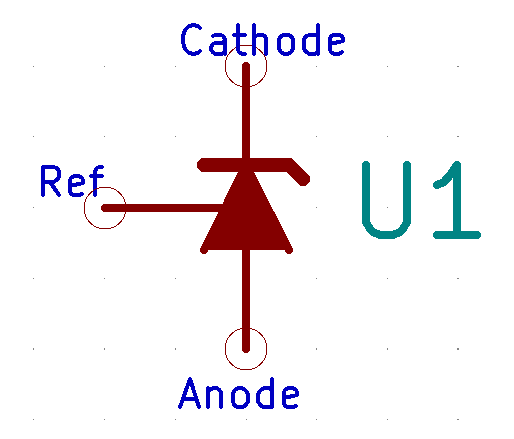
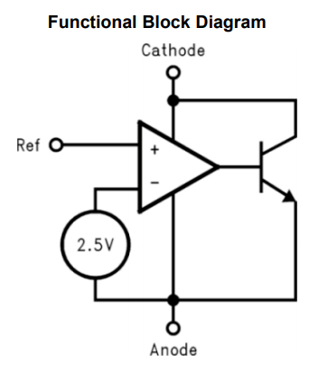
This can be confusing, as a three-pin shunt regulator is an IC (integrated circuit) that typically contains an op-amp, and BJT transistor along with the Zener! This is also reflected by the U IC designator prefix which is commonly used for these devices. The following image shows what actually is inside one of these devices:

The internal functional diagram of a three-pin shunt regulator. Note that there is much more to one of these than just a simple Zener diode! Image from https://www.ti.com/lit/ds/symlink/lm431.pdf, retrieved 2021-01-26.

The internal functional diagram of a three-pin shunt regulator. Note that there is much more to one of these than just a simple Zener diode! Image from https://www.ti.com/lit/ds/symlink/lm431.pdf, retrieved 2021-01-26.

Manufacturer Part Numbers

  • 431: Very common shunt regulator.
  • LM431: Shunt regulator from Texas Instruments based on the 431 series.

Authors

Geoffrey Hunter

Dude making stuff.

Creative Commons License
This work is licensed under a Creative Commons Attribution 4.0 International License .

Related Content:

Tags

comments powered by Disqus