Optical Isolators

Optical isolators (a.k.a. opto-isolators or optocouplers) are used to galvanically isolate two circuits while allowing data to pass between them. They are used to prevent high voltages from damaging sensitive electronics, prevent noise from one part of a circuit from affecting another part, and to communicate across circuits which must be isolated for safety reasons.
Types:
- Phototransistor optocouplers: A phototransistor is used to drive the output.
- Phototriac optocouplers.
Opto-isolators are similar to relays. The key differences are:
- Relays are typically used for turning on and off high current loads, while opto-isolators are used for communication (i.e. signals/low current).
- Relays have been traditionally electro-mechanical (although solid-state relays are available), while opto-isolators have always generally been solid-state.
Phototransistor Optocouplers
Schematic Symbol
A commonly used schematic symbol for a basic phototransistor-based optocoupler is shown below:
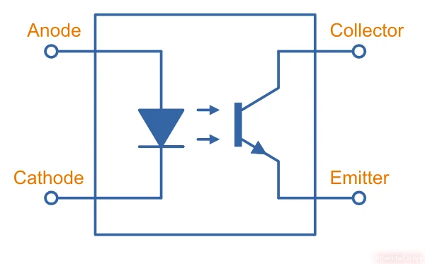
Many opto-isolators use a infrared emitting diode optically coupled to a phototransistor, all within a single enclosed component.
AC capable optocouplers usually have two LEDs in anti-parallel.
The Current-Transfer Ratio (CTR)
The current-transfer ratio (CTR) of a BJT-based optical isolator tells you how well it amplifies an input signal to an output signal. It is the ratio of the collector current at the output side relative to the forward current going through the LED on the input side, and then expressed as a percentage1:
For optical isolators with a single phototransistor driver, the current-transfer ratio is normally in the 20-400% range. Sometimes within a family there are multitude of parts with different transfer ratios, specified by slightly different part numbers. The EL3H7-G series from Everlight is one such example.
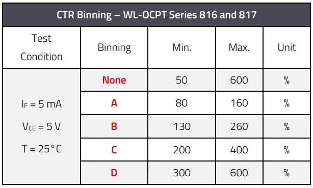
The current transfer ratio is specified at a particular forward current through the diode and particular voltage across the output collector-emitter .
Bidirectional Phototransistor Opto-isolators
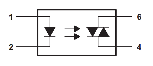
Opto-isolators can be made to support bidirectional inputs by adding a second photodiode in anti-parallel on the input side. This makes the opto-isolator turn on to both positive and negative input signals.
The schematic symbol for a bidirectional phototransistor opto-isolator is shown below:
Bidirectional opto-isolators are used often for AC. One example is the HCPL-354 by Avago.
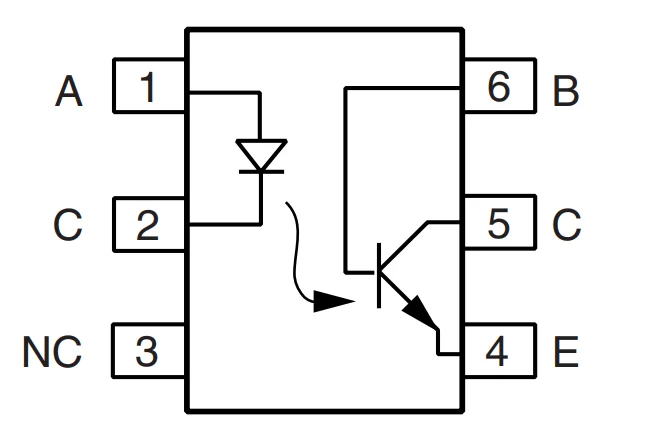
Phototransistor Optocoupler with a Base Pin
Some phototransistor-based optocouplers provide an electrical pin connected to the base of the phototransistor. With this pin, you can reduce the turn-off time of the optocoupler. To get the phototransistor to turn off quickly, you need remove the charge stored in the base-emitter junction. By adding a resistor in the approx. range of you can remove this charge quicker than it would naturally and increase the maximum speed the optocoupler can operate at2.
The downside is that adding a resistor here also reduces the CTR of the optocoupler24.
Another purpose of the base pin connection is to improve noise immunity. By connecting a capacitor between the base and the emitter, you can create a low-pass filter to improve the rejection of high-frequency noise/spikes. A capacitor is a good starting point5.
Supplier Links
Phototriac Output Optocouplers
Phototriac output optocouplers (a.k.a. triac couplers) are like phototransistor optocouplers, except they have a triac instead of a transistor on the output. The triac’s gate is controlled by the incoming light source. Phototriac optocouplers are used to switch on and off an AC load in an isolated manner.
The outputs of phototriac optical isolators usually go on to drive power TRIACs which switch a mains powered load.
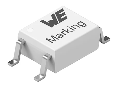
Component Packages
To achieve good isolation, different-net pins must be kept well away from each other to prevent arcing. This prevents many small-pitch packages from being used for optical isolators.
Some of the common packages used for optical isolation components are:
- The through-hole DIP package
- The surface-mount SOIC package.
- The surface-mound SOP-4 package.
Footnotes
-
Wurth Elektronik. Application Note - ANO007 - Understanding Phototransistor Optocouplers. Retrieved 2024-09-17, from https://www.we-online.com/components/media/o760909v410%20ANO007a_EN.pdf. ↩ ↩2
-
EEVblog. Purpose of the base on the opto-transistor in an opto-coupler [forum question]. Retrieved 2024-09-25, from https://www.eevblog.com/forum/beginners/purpose-of-the-base-on-the-opto-transistor-in-an-opto-coupler/. ↩ ↩2
-
Vishay. 4N25, 4N26, 4N27, 4N28 - Optocoupler, Phototransistor Output, with Base Connection [datasheet]. Retrieved 2024-09-25, from https://www.vishay.com/docs/83725/4n25.pdf. ↩
-
EDAboard. Floating base pin of optocoupler output transistor? [forum question]. Retrieved 2024-09-25, from https://www.edaboard.com/threads/floating-base-pin-of-optocoupler-output-transistor.402208/. ↩
-
Anindo Ghosh (2012, Nov 8). Optocoupler with base lead [question]. StackExchange. Retrieved 2024-09-25, from https://electronics.stackexchange.com/questions/48462/optocoupler-with-phototransistor-base-lead. ↩